CLICK HERE TO PRINT.
Introduction to Fuel Injection
Electronic fuel injection has replaced the carburetor as the dominate method of providing the correct amount of fuel to the engine in the power sports field.
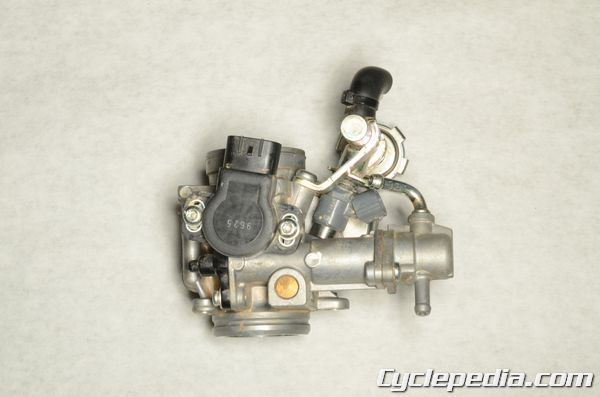
The throttle body is only the most obvious part of the fuel injection system. The real work is done by a host of sensors, controllers and the ECU.
Why is fuel injection better for the technician?
1. No separate fuel circuits to evaluate
2. Fewer moving parts
3. No carburetor cleaning
4. Self diagnostic trouble codes
How it works
Where a carburetor uses mechanical methods to provide the required fueling, the fuel injection system relies on a set of sensors and a computer to calculate and deliver the fuel needs.
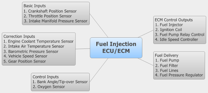
The Electronic Control Module (ECM), or Electronic Control Unit (ECU), is a small computer that receives input data from sensors. Based on the data from the sensors the ECM calculates the fuel injection and ignition needs of the engine. In real time, the ECM control outputs administer the fuel and ignition to the engine.
There are three sensors that provide the basic inputs the ECM needs to make the system function at a baseline level. The basic input sensors are the crank position sensor (CPS), manifold absolute pressure sensor (MAP), and throttle position sensor (TPS). The crank position sensor may be replaced or augmented by a camshaft position sensor on some models.
In addition to the basic inputs, fuel injection systems also have correction inputs to give the ECM additional information. These allow the ECM to adjust for maximum performance and efficiency based on varying conditions. Some common correction sensors are engine coolant temperature (ECT or WTS), intake air temperature (IAT), barometric pressure (BARO), vehicle speed, and gear position.
For overall engine running there are control input sensors. These are items like knock sensors, oxygen sensors, and bank angle/tip over sensors. These control inputs are in place to alert the ECM to a running condition that is outside of intended parameters. The ECM can then either adjust the ignition and fueling to a base level or shut the engine off if an unsafe running condition exists.
The ECM takes the information from the basic, corrective, and control inputs and then executes its fueling and ignition calculations with its control outputs. The ECM controls when and how long the fuel injector opens, when the ignition coil fires, and when the fuel pump operates via the fuel pump relay.
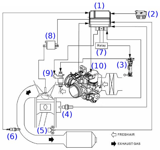
The diagram above shows the how the fuel injection components fit together. This is typical of most fuel injection systems. Usually off-road fuel injection systems will not use an oxygen sensor.
(1) ECM
(2) Bank Angle/Tip-over Sensor
(3) Fuel Pump
(4) Engine Coolant Temperature Sensor
(5) Crank Position Sensor
(6) Oxygen Sensor
(7) Fuel Pump Relay
(8) Ignition Coil
(9) Fuel Injector
(10) Throttle Body with MAP sensor, TPS, and ISC
Troubleshooting
A poorly running fuel injected machine fortunately has the ability to communicate to the mechanic what is wrong. An authorized dealership will have diagnostic equipment that will read trouble codes from the ECU, the same way trouble codes are read from an automotive system. In addition, nearly every motorcycle or ATV fuel injection system is equipped with a simple readout system where the fuel injection (FI) system light will blink in a series that will indicate the number of the trouble code that is stored. Using this information, the mechanic can then test the source of the indicated fault and soon be back to full running capability.
Unfortunately, not all diagnostic trouble codes are standard between brands, so there are no pat answers to code indications. Your best approach to investigating trouble code information is to look up your specific model in the Cyclepedia manuals or the manufacturer’s factory manual for a complete listing of possible codes and diagnostic procedures.
CLICK HERE TO PRINT.