CLICK HERE TO PRINT.
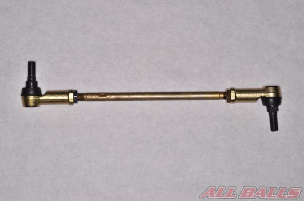
Ball Joint – Tie-Rod
SAFETY FIRST: Protective gloves and eyewear are recommended at this point.
Note: These instructions are very general, and you should have a service manual for your particular vehicle to get a better understanding of your particular setup and have factory recommended torque levels and specifications on hand.
Check out the Additional Service Information Resources [1] for more information on finding service information for your specific vehicle.
Prep
Thoroughly clean the vehicle to make the job easier and prevent contamination of the new components during installation.
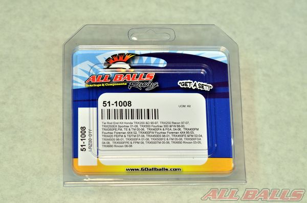
Get your tie-rod end kit from ALL BALLS RACING [2].
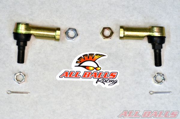
Remove the contents of your ALL BALLS RACING tie-rod end kit. Layout the components in an organized manner for easy installation. Note: wait to do this until the old parts are removed and you are ready to begin installing the new components.
Removal
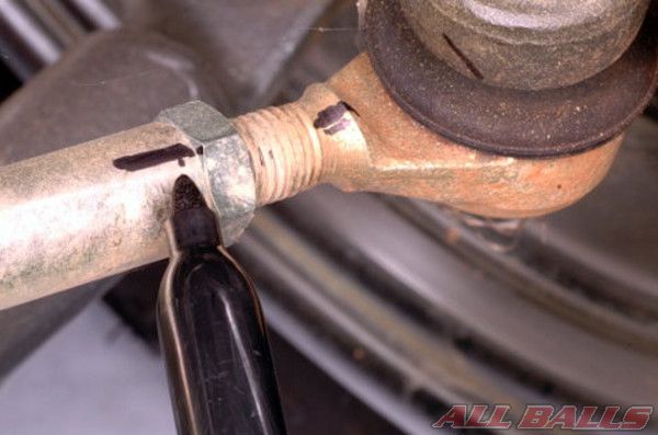
Remove the tie-rod nut cotter pins.
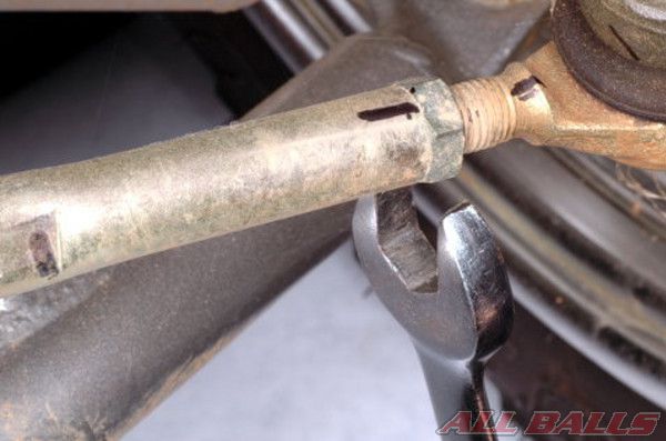
Remove the tie-rod nuts. It may be necessary to hold the tie-rod with a wrench when loosening the nut.
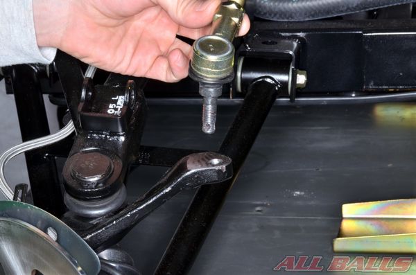
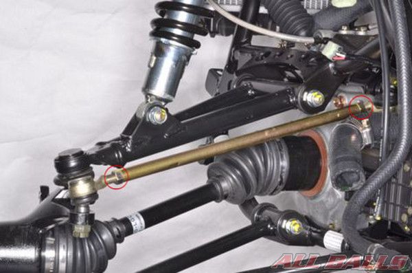
Free the tie-rod from the knuckle and steering shaft. See the vehicle’s service manual for specific information.
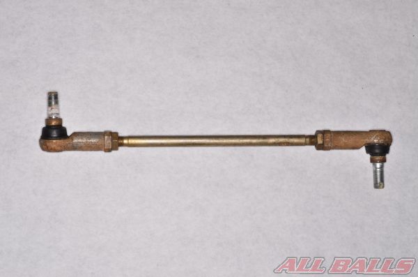
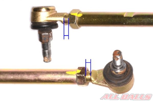
Inspect the tie-rod for wear and damaged. Note the position of the ends. Some vehicles have specific instructions for tie-rod length and end positioning. Check the service manual for the specific information for the vehicle.
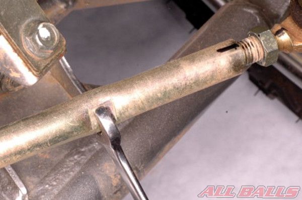
Mark the tie-rod for a starting point for reassembly.
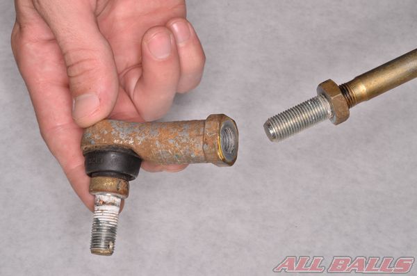
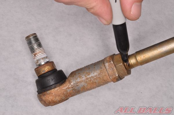
Remove the tie-rod end.
Note: usually the outer tie-rod end and lock nut have reverse threads.
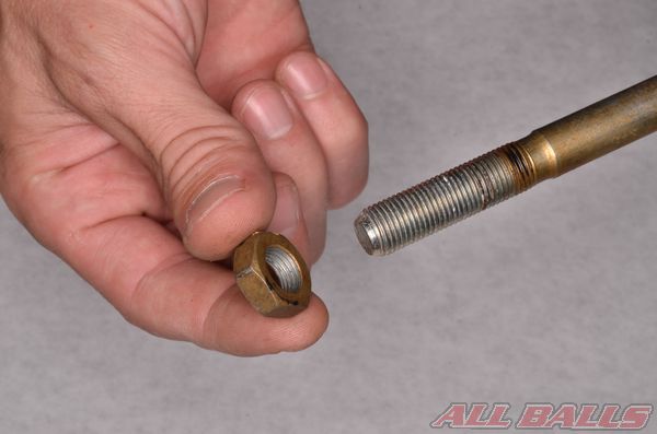
Remove the lock nut.
Installation
Install the new lock nut.
Note: usually the outer tie-rod end and lock nut have reverse threads.
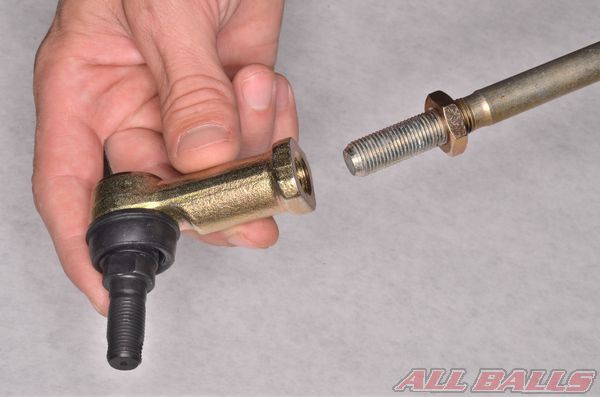
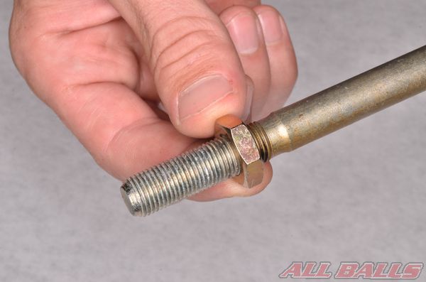
Install the tie-rod end onto the rod.
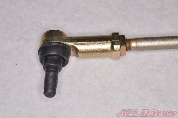
Tighten the lock nut against the tie-rod end to set the position.
Set the position and distance between the tie-rod ends according to the OEM requirements.
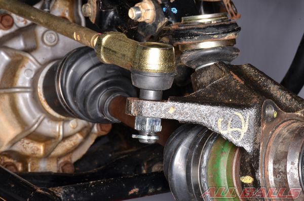
Install the tie-rod to the steering shaft and knuckle. Make sure the ends are positioned correctly so the ball joints are not at severe angles. Install new cotter pins with the ball joint nuts.
Assemble the vehicle and inspect the Toe-in alignment.
Toe-in specifically refers to the amount the front wheels are pigeon toed. At axle level the center of the front tires are closer in the front than in the back. Most ATVs and side-by-sides call for the front wheels to be slightly pigeon toed to parallel for good stability.
Keeping the toe-in aliment in specification and adjusted correctly is important for performance, safety, and tire wear. If the front end of the vehicle is in a toe-out position, duck footed, the tires will wear more rapidly and the vehicle will be inherently unstable. In addition, if the toe-in adjustment is in specification but it has been improperly adjusted it may put excess strain on the steering components. The front wheel alignment with the handlebar can be thrown off if the tie-rods are adjusted unevenly.
The first step in checking the toe-in is to check the tire pressure. Make sure the tire pressure set correctly in all four tires. The air pressure in the front tires should be as close to the same as possible.
Place the vehicle on a level surface and position the steering straight ahead. The handlebar must be positioned straight ahead. Measure the handlebar position on each side to confirm this. Do not change the handlebar position from straight ahead.
Note: Some models should have the toe-in inspected and set with the front tires resting on the ground, while others specify the front wheels should be elevated. Consult the service manual for the particular model for detailed instructions and specifications for this procedure.
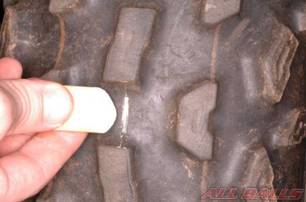
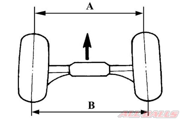
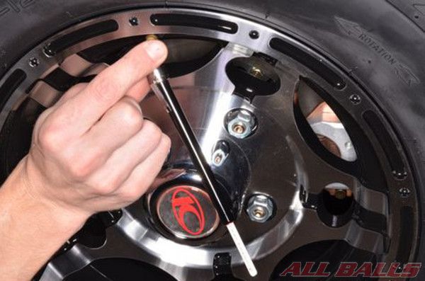
Make a chalk mark on the front, center of each front tire at the height of the front axle. If available set up a toe gauge so that the pointers line up with the chalk marks.
Measure the distance between the front chalk marks. Record this measurement as A. Rotate the front wheels 180° so the marks remain at axle height, but are now facing to the rear. Record the distance between the marks on the backside of the tires as B. Subtract the front measurement A from the rear measurement B to calculate the toe-in. If the number is negative you have a toe-out condition. Compare your toe-in figure with the factory specification found in the vehicle’s service manual.
Mark the tie-rods for reference.
To adjust the toe-in loosen the lock nuts on the tie-rods.
The outer or inner tie-rod lock nuts must have reverse threads. Usually it is the outer nuts, but in some cases it can be the inner nuts.
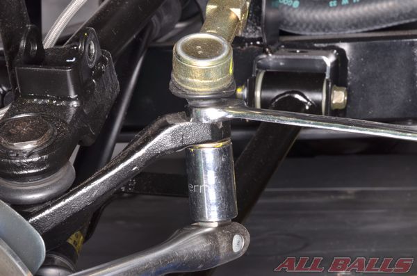
Turn the tie rods with a wrench at the flats to change the toe-in. Evenly adjust the left and right tie-rods for proper alignment.
Check with the service manual to see if there are any specifications for the length of the tire rods or the amount of threads that should be showing. If the tie-rods are not adjusted according to the OEM specifications the proper toe-in may be achieved, but the vehicle will not steer correctly and it could be at risk of breaking a tie-rod.
When the adjustment is correct hold the tie-rod flats and tighten the lock nuts to specification against each side of the tie-rod. Take a slow test ride to make sure the steering functions correctly.
INSTALL ALL BALLS RACING STICKER!
URLs in this post:
[1] Additional Service Information Resources: http://www.cyclepedia.com/manuals/online/cpp-all-balls/additional-service-information/
[2] ALL BALLS RACING: http://www.allballsracing.com/
CLICK HERE TO PRINT.