
The Yamaha V-max showed up in 1985 and ran for more than 20 years in its first generation form. Derivatives of this V-4 engine were also used in the Venture, Venture Royale and Royal Star models. The firing order of this engine is cylinder: #1 (0°), #3 (180°), #2 (430°), #4 (610°). There is a 70° gap between the combustion strokes of #3 and 2 cylinders, and a 70° overlap of the combustion strokes of the #4 and #1 cylinders. A traditional inline 4-cylinder has four perfectly spaced combustion stokes, one every 180°, without any gaps or overlaps. Setting the engine timing or checking the valve clearance can be a little intimidating with an atypical engine configuration.
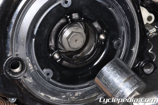
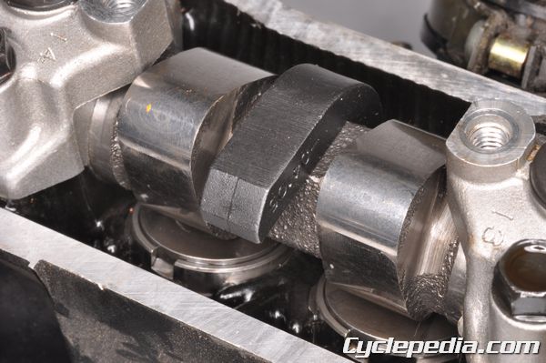
The cylinder must be positioned at TDC on the compression stroke to check that cylinder’s valve clearance. Start with the #1 cylinder (rear left). Use a 32 mm socket wrench to turn the crankshaft counterclockwise and observe the flywheel as it moves past the timing hole. Stop when the T1 mark is aligned with the stationary pointer in the timing hole. Cylinder #1 is at TDC when the T1 mark is aligned with the stationary pointer and the intake and exhaust cam lobes for cylinder #1 are pointing away from each other.

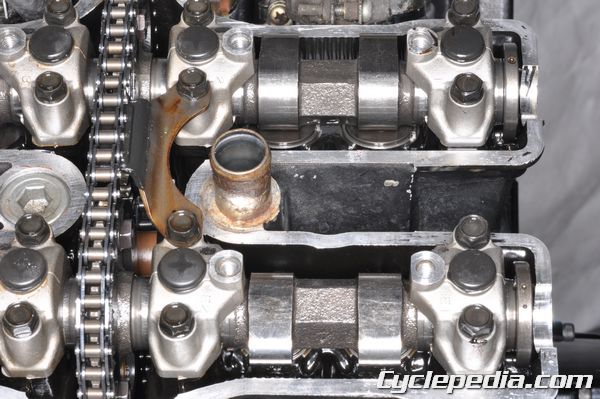
Measure the clearance between the camshaft and lifter shim. Record the valve clearances for this cylinder.
The next cylinder to be checked is #3 (rear right). Rotate the crankshaft counterclockwise 180° from cylinder #1 inspection point in order to set cylinder #3 to TDC on the compression stroke. There isn’t a T3 mark on the flywheel, but make sure the cam lobes are pointing away from each other. Measure and record the valve clearances for this cylinder.
The #2 cylinder (front left) is up next. Turn the crankshaft counterclockwise 250° from the #3 TDC compression stroke position (430° from T1) so the T2 mark aligns with the stationary pointer and the cam lobes are in the correct position. Check and record the valve clearances for cylinder #2.
Lastly, check the valve clearances for cylinder #4 (front right). Turn the crankshaft counterclockwise 180° from T2 (610° from T1) and make sure the #4 cylinder cam lobes are in the TDC compression stroke position. Check and record the valve clearances for cylinder #4.

Fortunately the camshafts can remain in the cylinder head for a shim change with the use of the Yamaha special tappet adjusting tool (Part No. YM-33961).

Position the valve lifters so the shim grooves are accessible.
Fit the tool onto the camshaft so that the tool’s lifter contacts are opposite the cam lobe.

Turn the tool to rotate the camshaft until the tappet tool depresses the valve lifters, not the shims.
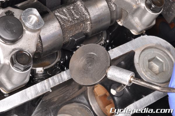
Use a small flat blade screwdriver to separate the shims from the lifter. Use a pair of tweezers, small screwdriver, or a magnet to remove the valve shims from beneath the cam lobes. Measure the shim thickness and use the recorded valve clearance to determine the correct replacement shim. Install the new shim/s and rotate the camshaft to free the special tool. Replace the shims to bring the clearance into specification for all valves as necessary.
Working with a multi-cylinder engine with an uncommon firing order can be a headache. Take some time and read through the service manual. If possible, rotate the engine with the valve covers removed so the valve timing can be viewed in real life. When in doubt, make sure that the cylinder being inspected is at TDC on the compression stroke when checking the valve clearance.


Leave a Reply
You must be logged in to post a comment.