CLICK HERE TO PRINT.
Switches
 Like this Manual?
SAFETY FIRST: Protective gloves and eyewear are recommended at this point.
To test these switches, you will need a digital multimeter set to Ω (Ohms of resistance). If a switch does not meet specification replace it.
Water Temperature Switch
See the Thermostat [2] topic.
Radiator Fan Switch
See the Radiator [3] topic.
Ignition Switch
Remove the front fender. See the Front Fender [4] topic.
Unplug the 3-pin ignition switch connector. There should be continuity between the wires in the ON position, and no continuity between any of the three wires in the OFF position.
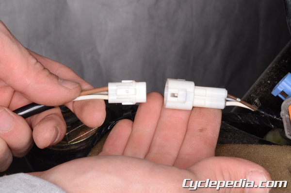
Handlebar Switches
Remove the front fender to access the handlebar switch connectors. See the Front Fender [4] topic.
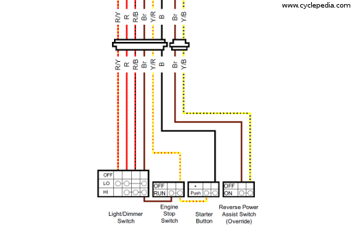
Test the handlebar switches for continuity as indicated by the wiring diagram. See the Wiring Diagrams [5] topic to see the wiring diagrams.

The 2WD/4WD switch has a blue 2-pin connector. There should be continuity in 2WD only.

There are two connectors to the left handlebar switches.
The front brake switch has a 2-pin connector. The rear brake switch has two bullet connectors.
Neutral and Reverse Switches
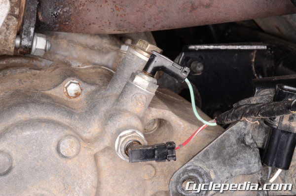
The neutral and reverse switches are located to the rear of the engine oil dip stick.
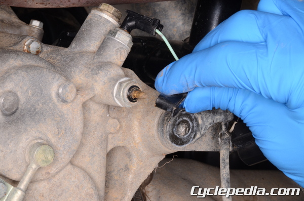
Unplug the neutral and reverse switch connectors.
Check for continuity between the switch terminal and a ground.
There should only be continuity for the neutral switch when the transmission is in neutral.
There should only be continuity for the reverse switch when the transmission is in reverse.
Use a deep well 14 mm socket to replace the reverse or neutral switches as needed.
Neutral / Reverse Position Switches: 15 N-m, 1.5 kgf-m, 11
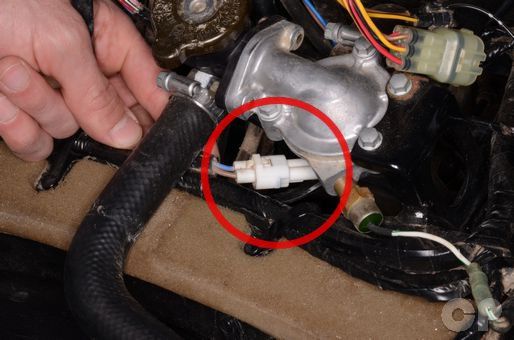
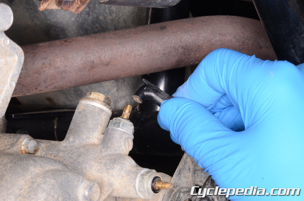
Oil Pressure Switch Switch
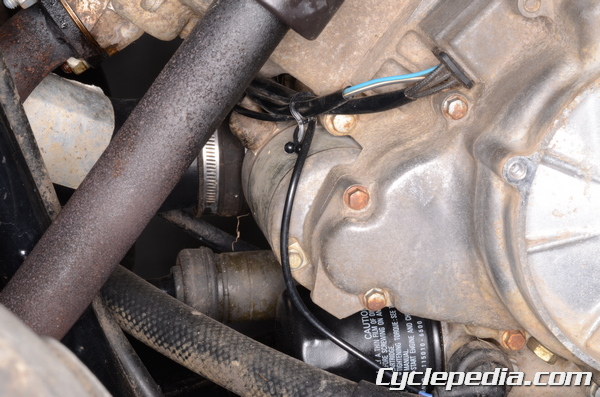
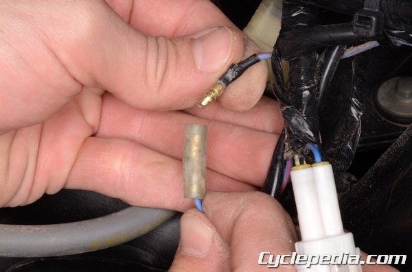
Follow the oil pressure switch wire up from the bottom left of the engine. Unplug the oil pressure switch bullet connector.
Check for continuity between the switch wire and a ground.
There should only be continuity when the engine is not running.
Belt Failure Detection Switch
The belt failure detection switch is located inside the CVT cover. See the CVT Cover [6] topic for more information.
If the switch is damage or not working correctly the cover must be replaced as a whole.

There should be continuity between the switch wires only with the switch in the ON position.
URLs in this post:
[1] Image: https://www.repairmanual.com/product/kawasaki-kvf650-brute-force-kvf650-kvf700-prairie-suzuki-twinpeaks-700-atv-printed-service-manual/
[2] Thermostat: https://www.cyclepedia.com/manuals/online/cpp-153/cooling-system/thermostat/#Water
[3] Radiator: https://www.cyclepedia.com/manuals/online/cpp-153/cooling-system/radiator/#Inspecti
[4] Front Fender: https://www.cyclepedia.com/manuals/online/cpp-153/external-components/front-fender/
[5] Wiring Diagrams: https://www.cyclepedia.com/manuals/online/cpp-153/electrical-systems/wiring-diagrams/
[6] CVT Cover: https://www.cyclepedia.com/manuals/online/cpp-153/converter-system/cvt-cover/
CLICK HERE TO PRINT.