
 Like this Manual?
SAFETY FIRST: Protective gloves and eyewear are recommended at this point.
Removal
Be sure that the ignition is in the OFF position.
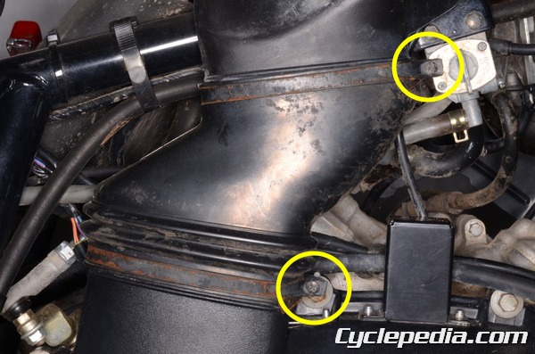
Loosen the air duct clamp screws with a #2 Phillips screwdriver.
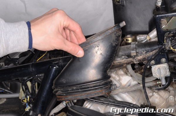
Remove the air duct.
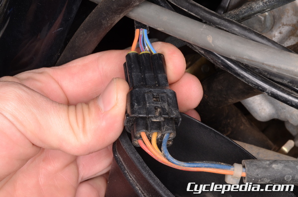
The engine braking actuator doesn’t have to be removed to take off the cover. Trace the wires up from the engine braking actuator. For more information on the engine braking actuator see the Actuators topic.
Unplug the engine braking actuator connector.

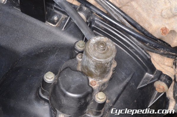
On the right side above the ignition coil there is a group of wires secured by two clamps.

Open the wire clamps.

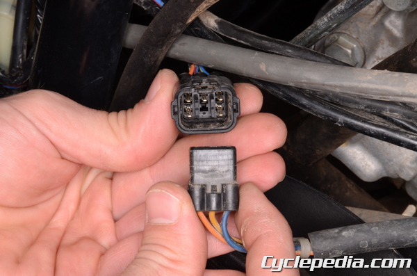
Locate the dive belt failure detector 2-pin connector and unplug it.

Remove the rear brake light switch spring from the pedal.
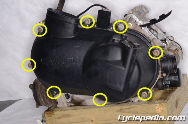
Loosen the eight CVT cover bolts with a 10 mm socket.
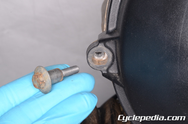
Remove each bolt.
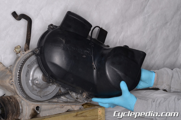
Remove the CVT cover.
Engine Brake Actuator Lever
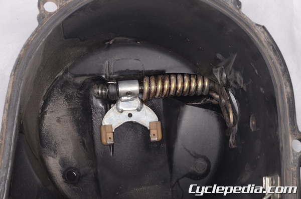
The CVT cover houses the engine brake actuator lever assembly.
Measure the width of the wear on guide shoes on the fork and replace the fork if the wear exceeds 6 mm (0.24 in).
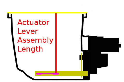
Measure the distance between the CVT cover opening and the resin tips of the actuator lever fork.
The length of the actuator lever assembly should be 149.33 – 150.47 mm (5.879 – 5.924 in).
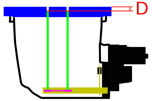
Use the special measuring tool to check if the actuator lever assembly has the correct components. Install the plate (blue) and bolt it to the cover. The rods (green) must rest on the resin tips of the fork.
Special Tool – Actuator Lever Measurement Tool: 57001-1499
Measure the depth of the rods below the top of the plate (D).
The measurement (D) should be 1.33 – 2.47 mm (0.052 – 0.097 in).
If the measurement is below the standard the actuator lever assembly should be replaced with the part number 13236-0046 with a yellow paint mark. If the measurement is above the standard the actuator lever assembly should be replaced with the part number 13236-0047 with a green paint mark. After the parts are replaced recheck the measurement (D) with the special tools.
If the measurement is still out of specification replace the CVT cover and change out the actuator lever assembly with the part number 13236-0048.
Installation
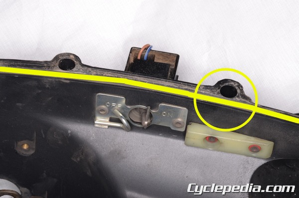
Make sure the belt detection switch is in the ON position. If the switch is in the OFF position this will limit the engine RPM. Install the cover seal so that its joint is on the top and under the cover hole as indicated.
Fit the CVT cover to the crankcase.
Install the eight CVT cover bolts. Tighten the bolts a little bit at a time in a crisscross patter. Torque the bolts to specification with a 10 mm socket.
CVT Cover Bolts: 8.8 N-m, 0.9 kgf-m, 78 in-lb

Plug in the dive belt failure detector 2-pin connector.
Secure the wires with the wire clamps.
Plug in the engine braking actuator connector.
Install the air duct. Tighten the air duct clamp screws securely with a #2 Phillips screwdriver.
Connect the rear brake light switch spring to the pedal.