
 Like this Manual?
SAFETY FIRST: Protective gloves and eyewear are recommended at this point.
Information
The Drive Belt Check system records the amount of hours your ignition is energized via an hour-meter. The hour-meter records actual motor running time as well as any span of time that the key turned is in the ON position. When 100 hours have accumulated on the hour-meter, the Belt Check Indicator light will trigger indicating the drive belt needs to be inspected and possibly replaced. The Belt Check Indicator will remain lit until it is reset.
The Drive Belt Failure Detection System consists of a switch mounted on the CVT cover that can be tripped by a worn or damaged belt. If the Drive Belt Failure Detection switch trips, the Belt Check Indicator light will flash, and the vehicle will switch into “slow mode.” In slow mode, the engine speed is limited to 3600 rpm, and you will not be able to engage the transmission into 4 wheel-drive.
2002 Models
Kawasaki KVF650-A1/B1 models are equipped with a Drive Belt Failure Detection Switch that is located on the continuously variable transmission (CVT) cover. The cover must be removed to gain access to the switch so that it can be reset. The system also consists of an hour-meter that is integrated into the Liquid Crystal Display (LCD) panel of your instrument cluster.
The 2002 Prairie does not have a belt check indicator light. When the Drive Belt Failure Detection Switch is tripped the reverse indicator light and the LCD display will flash repeatedly indicating that it needs to be reset.
2003 and Newer Models
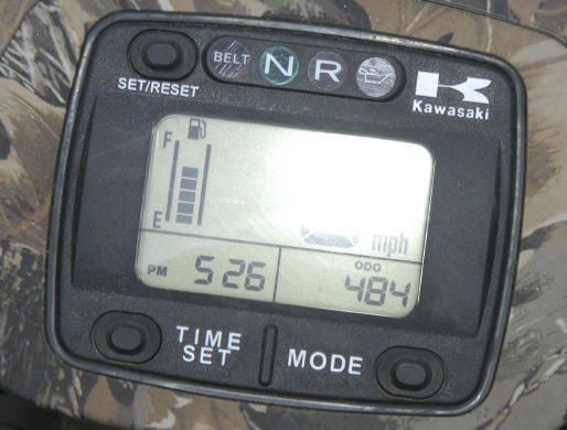
These models are equipped with both an hour-meter and Drive Belt Failure Detection System. In addition to a Belt Check Indicator light these models feature a digital hour meter/trip meter/odometer on the instrument cluster. You can toggle to the hour meter mode by pressing the Mode button. The Belt Check Indicator light is triggered after 100 hours of operation.
If your Belt Check Indicator light is on you can assume the hour-meter has logged at least 100 hours of running time. The drive belt should be inspected before operating the ATV any further. After inspecting and or replacing the drive belt you can then reset the Belt Check system.
If your Belt Check Indicator light is flashing and your ATV will not rev more than 3600 rpm or engage into 4 wheel-drive, it has been put into “slow mode”. The drive belt should be inspected before operating the ATV any further. After inspecting and or replacing the drive belt you can then release the Drive Belt Failure Detection system.
Process

Turn the ignition switch to the OFF position.
Remove the CVT cover. See the CVT Cover topic.
Inspect the belt. See the Belt Inspection topic.

Locate the Drive Belt Failure Detection Switch. Move the Drive Belt Failure Detection Switch to the ON position. The ON position is towards the back of the machine. If the switch has been tripped you should see it in the forward position when you remove your CVT cover.
2002 Models

Install the CVT cover and plug in the Drive Belt Failure Detection Switch 2-pin connector.
Turn your ignition key to the ON position and verify that the indicator is no longer flashing.
2003 650 and all 700 Models
Install the CVT cover and plug in the Drive Belt Failure Detection Switch 2-pin connector.

On the right side above the ignition coil there is a group of wires secured by two clamps.

Open the wire clamps.
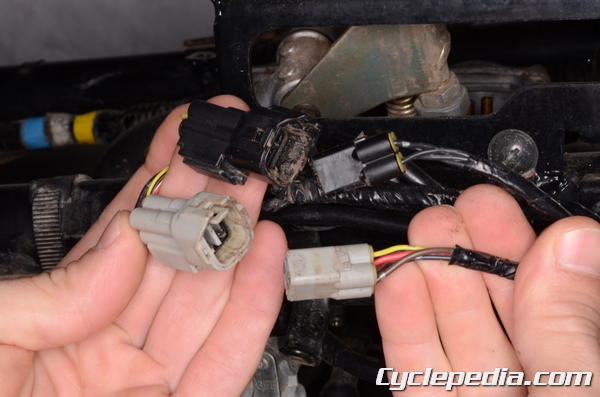
Disconnect the black and gray 4-pin connectors so that you have 2 male pieces and 2 female pieces.

Connect the gray male 4-pin connector into the black female 4-pin connector. The female connector is the receptacle part of the connection. Also connect the black male 4-pin connector into the gray female 4-pin connector.
Turn the ignition switch to the ON position.

Locate the dive belt failure detector 2-pin connector and unplug it.
Observe the Belt Check Indicator on your instrument cluster. The light should flash on and off. Let it flash for at least five seconds.
Turn the ignition switch to the OFF position.
Turn the ignition switch to the ON position.
Observe the Belt Check Indicator on your instrument cluster. The light should flash on and off. Let it flash for at least five seconds.
Turn the ignition switch to the OFF position.
Disconnect the mismatched black and gray connectors and plug them into their correct color mates.
Plug in the dive belt failure detector 2-pin connector.
Turn your ignition key to the ON position and verify that the indicator is no longer flashing.
Repeat the procedure as needed. Return the wires to the clamps and install any removed components.
2005 – 2006 650 Models
Install the CVT cover and plug in the Drive Belt Failure Detection Switch 2-pin connector.
On the right side above the ignition coil there is a group of wires secured by two clamps.
Open the wire clamps.
Disconnect the black and gray 4-pin connectors so that you have 2 male pieces and 2 female pieces.
Connect the gray male 4-pin connector into the black female 4-pin connector. The female connector is the receptacle part of the connection. Also connect the black male 4-pin connector into the gray female 4-pin connector.
Turn the ignition switch to the ON position.
Observe the Belt Check Indicator on your instrument cluster. The light should flash on and off quickly.
Locate the dive belt failure detector 2-pin connector and unplug it.
Observe the Belt Check Indicator on your instrument cluster. The light should flash on and off slowly. Let it flash for at least five seconds.
Turn the ignition switch to the OFF position.
Disconnect the mismatched black and gray connectors and plug them into their correct color mates.
Plug in the dive belt failure detector 2-pin connector.
Turn your ignition key to the ON position and verify that the indicator is no longer flashing.
Repeat the procedure as needed. Return the wires to the clamps and install any removed components.
2007 and Newer 650 Models
Install the CVT cover, but leave the in the Drive Belt Failure Detection Switch 2-pin connector unplugged.
On the right side above the ignition coil there is a group of wires secured by two clamps.
Open the wire clamps.
Disconnect the black and gray 4-pin connectors so that you have 2 male pieces and 2 female pieces.
Connect the gray male 4-pin connector into the black female 4-pin connector. The female connector is the receptacle part of the connection. Do not plug the black male connector into the gray female connector.
Turn the ignition switch to the ON position.
Observe the Belt Check Indicator on your instrument cluster. The light should flash on and off quickly (approx. 0.4 second interval) five times and then flash slowly (approx. 1 second interval).
Allow the light to flash slowly for at least 2 seconds, and then Turn the ignition switch to the OFF Position.
Disconnect the mismatched black and gray connectors and plug them into their correct color mates.
Plug in the dive belt failure detector 2-pin connector.
Turn your ignition key to the ON position and verify that the indicator is no longer flashing.
Repeat the procedure as needed. Return the wires to the clamps and install any removed components.