
 Like this Manual?
SAFETY FIRST: Protective gloves and eyewear are recommended at this point.
Removal
The piston must be positioned at top dead center, on the compression stroke, for the cylinder that the cylinder head cover is to be removed. Here is how to do it.
Remove the valve adjusting cover bolts with an 8 mm socket.
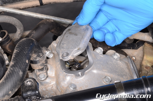
Lift off the valve adjusting covers.
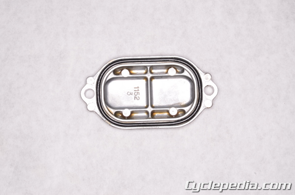
Inspect the valve adjusting cover O-rings and replace them as needed.
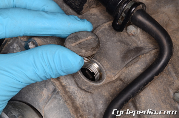
Remove the timing inspection plug with a filler cap driver. Inspect the inspection plug O-ring and replace as needed.
Special Tool – Filler Cap Driver: 57001-1454
Front Cylinder Head Cover
Remove the side covers. See the Side Covers topic for more information.
Remove the front fender. See the Front Fender topic for more information.
Remove rear inner covers. See the Inner Covers topic for more information.
Remove the recoil starter. See the Recoil Starter topic for more information.

Turn the crankshaft counterclockwise with a 19 mm socket.
Rotate the crankshaft counterclockwise until you observe the intake valves of the front cylinder head open and then close. You will see the valves move downward as they open and move upwards as they close.
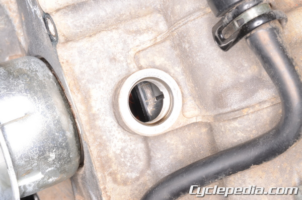
Stop the turning the crankshaft when the “T-F” mark on the generator rotor aligns with the indicator on the case cover.
Remove the front cylinder cam chain tensioner only. See below for more information.
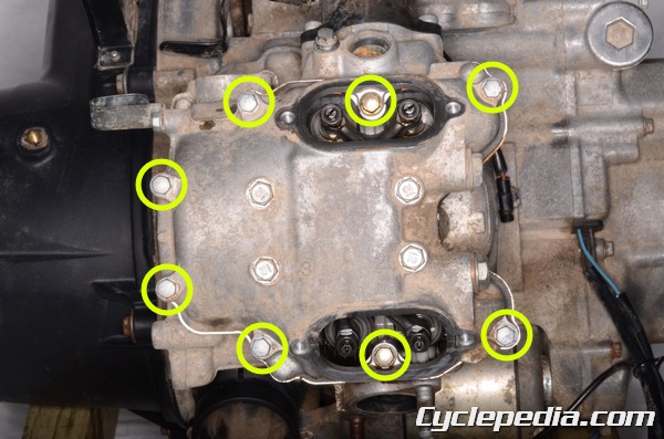
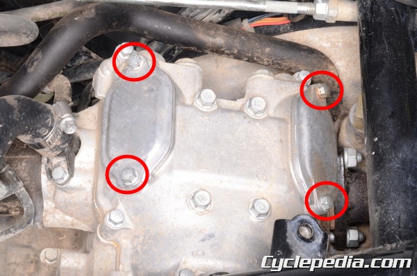
Remove the eight smaller cylinder head cover bolts with an 8 mm socket.
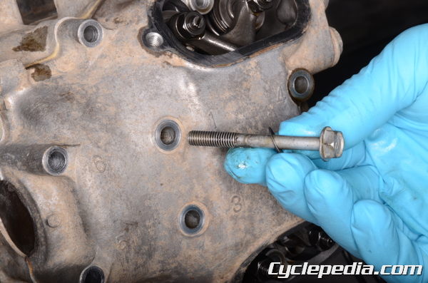
Remove the four larger central bolts and washers with a 10 mm socket.
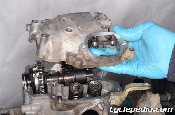
Remove the front cylinder head cover.
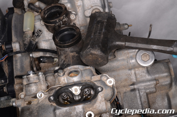
Tap the reinforced areas of the cylinder head cover if need to free it.
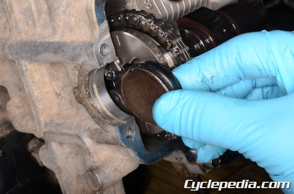
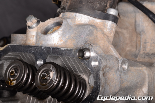
Remove the surface cap from the cam sprocket side of the cylinder head.

Remove the two dowel pins. For information on the camshaft see the Camshafts topic. For information on the rocker arms see the Rocker Arms topic.
Rear Cylinder Head Cover
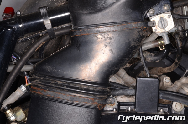
The converter air duct must be removed.

Loosen the air duct clamp screws with a #2 Phillips screwdriver.
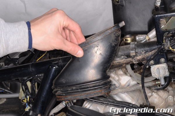
Remove the air duct.
Turn the crankshaft counterclockwise with a 19 mm socket until you observe the intake valves of the rear cylinder head open and then close. You will see the valves move downward as they open and move upwards as they close.

Stop the turning the crankshaft when the “T-R” mark on the generator rotor aligns with the indicator on the case cover.
Remove the rear cylinder cam chain tensioner. See below for more information.
Remove the rear cylinder head cover and rocker arms as with the front. See above for more information.
Installation
Make sure the cylinder head cover mating surface is clean. The rocker arms must be installed. See the Rocker Arms topic for more information.
The cylinder head covers, like the camshafts, must be installed with the corresponding piston at TDC on the compression stroke. For more information on the camshaft installation see the Camshafts topic.
Rear Cylinder Head Cover
The rear piston will be at TDC when the “T-R” mark is aligned with the indicator in the timing hole. The rear cylinder cam lobes should be facing down. For more information on the camshaft installation see the Camshafts topic.
Install the two cylinder head cover dowel pins.
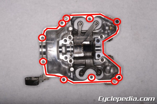
Apply liquid gasket to the cylinder head cover mating surface as indicated. Do not allow the gasket material to contact the rocker arms or get in the camshaft journal areas.
Sealant – Liquid Gasket TB1216: 92104-1063
Also, apply liquid gasket to the outside circumference of the surface cap. Fit the surface cap into place on the cam sprocket side of the head. Fit the cylinder head cover into place.
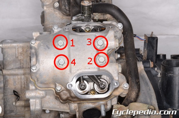
Insert the four larger diameter cylinder head cover bolts with washers. Tighten these bolts to specification with a 10 mm socket in a crisscross pattern.
Rocker Case Bolts (Larger): 8.8 N-m, 0.9 kgf-m, 78 in-lb
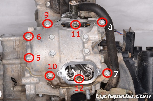
Install the smaller diameter bolts with an 8 mm socket. Tighten the bolts to specification evenly in the order shown.
Bolt Number / Bolt Length
5 – 6: 130 mm (5.1 in.)
7 – 10: 30 mm (1.2 in.)
11 – 12: 25 mm (1.0 in.)
Rocker Case Bolts (Smaller): 9.8 N-m, 1.0 kgf-m, 87 in-lb
Install the rear cylinder cam chain tensioner only. See below for more information.
Double check the engine timing and check the valve clearance. See the Valve Adjustment topic for more information.
Install the air duct.

Tighten the air duct clamp screws securely with a #2 Phillips screwdriver.
Front Cylinder Head Cover
The front piston will be at TDC when “T-F” mark on the generator rotor aligns with the indicator on the case cover. The front camshaft lobes should be facing down. For more information on the camshaft installation see the Camshafts topic.
Install the front cylinder head cover in the same manner as the rear.
Install the rear cylinder cam chain tensioner. See below for more information.
Double check the engine timing and check the valve clearance. See the Valve Adjustment topic for more information.
Install the recoil starter. See the Recoil Starter topic for more information.
Install rear inner covers. See the Inner Covers topic for more information.
Install the front fender. See the Front Fender topic for more information.
Install the side covers. See the Side Covers topic for more information.
Cam Chain Tensioner
Removal
The process to remove both cam chain tensioners is the same. Do not rotate the crankshaft while the cam chain tensioner/s are not installed unless the cylinder head covers with rocker arms have been removed.
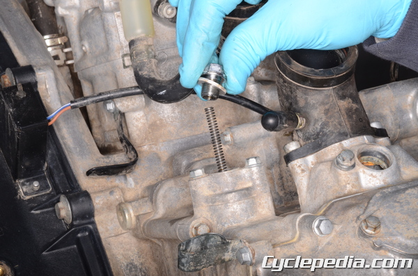
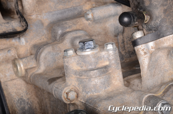
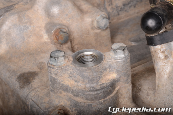
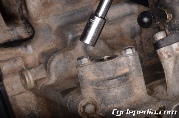
Loosen the cam chain tensioner cap bolt with a 12 mm socket. Remove the cam chain tensioner cap bolt and sealing washer.
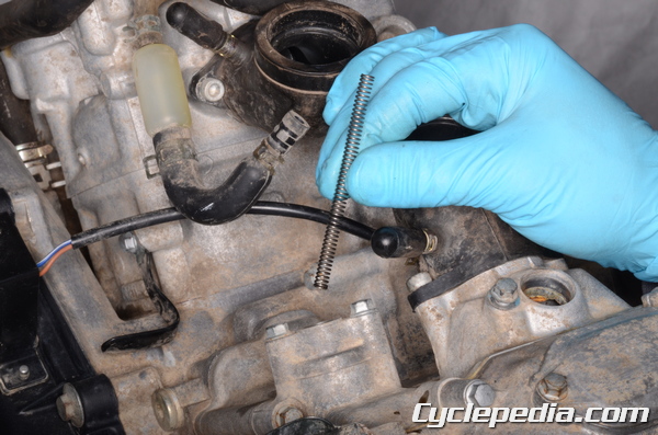
Remove the cam chain tensioner spring.
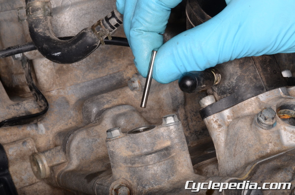
Remove the cam chain tensioner pin.
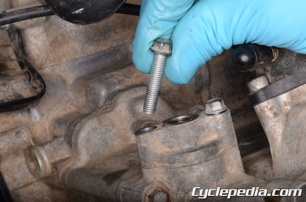
Remove the two cam chain tensioner mounting bolts with an 8 mm socket.
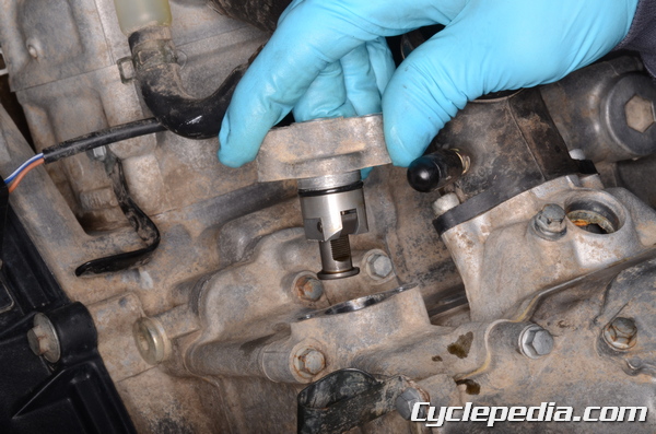
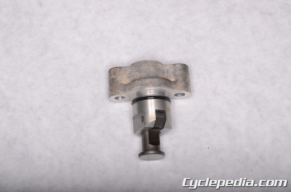
Remove the cam chain tensioner from the cylinder.
Installation
Replace the cam chain tensioner O-ring with a new one.
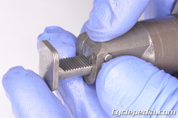
Push in on the ratchet and push the tensioner rod all the way into the body.
Fit the tensioner into the cylinder. Thread in the two mounting bolts.
Tighten the cam chain tensioner bolts to specification with an 8 mm socket.
Chain Tensioner Mounting Bolts: 8.8 N-m, 0.9 kgf-m, 78 in-lb
Install the pin into the tensioner body.
Install the spring.
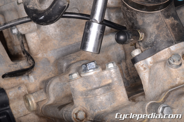
Install the cam chain tensioner cap bolt with sealing washer. Tighten the cap bolt to specification with a 12 mm socket.
Chain Tensioner Cap Bolts: 22 N-m, 2.2 kgf-m, 16 ft-lb
Make sure the engine timing is correct before running the engine or damage will occur.