
 Like this Manual?
SAFETY FIRST: Protective gloves and eyewear are recommended at this point.
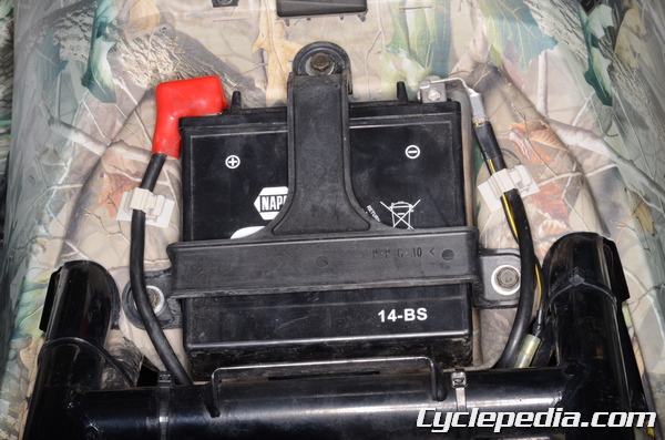
Make sure the battery is fully charged. See the Battery topic for more information.
You will need a digital multimeter to inspect the charging system.
Special Tool – Hand Tester: 57001-1394
Battery
See the Battery topic for more information.
Alternator
Output Voltage

The three pin alternator connector is located next to the regulator/rectifier on the back right side of the frame.
Turn the ignition switch off.
Set the multimeter to read voltage (VAC 250).
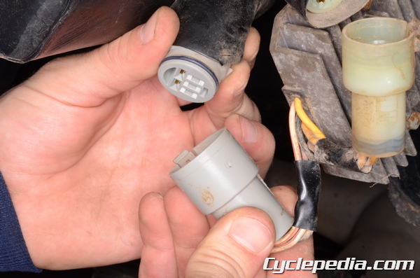
Unplug the 5-pin alternator connector.
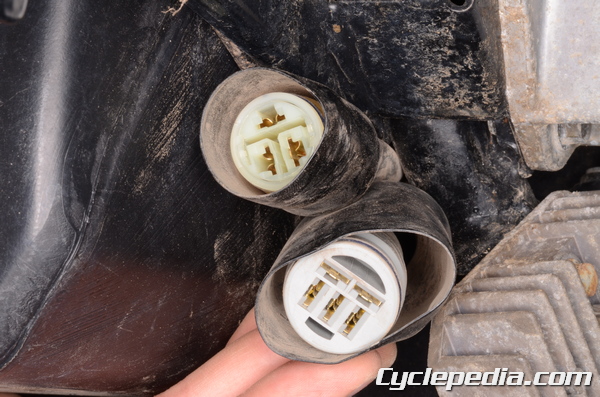
Touch a multimeter tester probe to each black wire terminal on the harness side of the connector.
Start the engine and test the voltage at the given rpm. Perform at least three measurements.
Alternator Output Voltage: 39 ~ 59 V 3,000 rpm
If the output is low or nonexistent either the alternator flywheel has lost magnetism, or has a short or open lead in the alternator.
If the output voltage is in specification, but the charging system is not functioning correctly there is a problem with the regulator/rectifier.
Stator Coil Inspection
Turn the ignition switch off.
Unplug the 5-pin alternator connector.
Set the multimeter to read ohms of resistance (1 x Ω).
Touch a multimeter tester probe to each black wire terminal on the harness side of the connector. Measure the resistance.
Stator Coil Resistance: 0.33 ~ 0.49 Ω
If there is not resistance the stator coil has an open lead. If the resistance is otherwise out of specification there may be a short.
If the stator coil resistance is in specification, but the alternator output voltage is low this could be the result of an alternator flywheel that has reduced magnetism.
For information on replacing the stator coil and flywheel see the Alternator topic.
Regulator/Rectifier
Regulated Voltage
Remove the seat. See the Seat topic for more information.
Turn the ignition switch off.
Set the multimeter to read voltage (VDC) and connect the probes to their respected battery terminals.
Connect a tachometer.
Start the engine and let it warm up to for several minutes. Test the voltage with the lights on and off. At low rpm the voltage should be near the battery voltage and it should increase with rpm. Rev the engine to 5,000 rpm and measure the voltage.
Charging Voltage (Regulator/rectifier output voltage): 14 ~ 15 V
Regulator/Rectifier Resistance Inspection
Set the multimeter to read ohms of resistance.
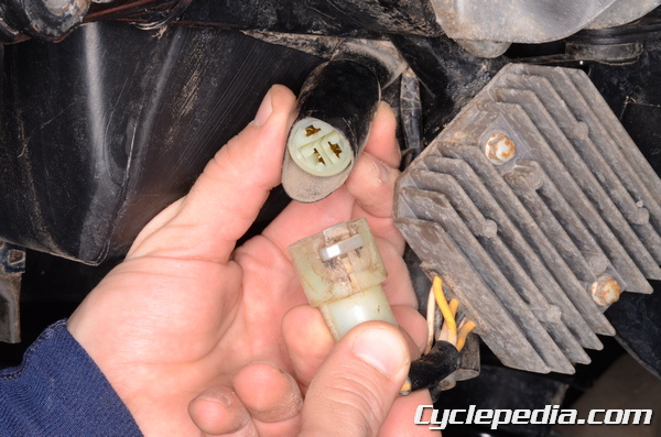
Unplug the 3-pin alternator connector.
Unplug the 5-pin alternator connector.
Check the resistance between the terminals as indicated. Check with the meter probes one direction and then flip them. The readings should show low resistance one direction and 10 times as much the other. If the readings are both high or low the rectifier must be replaced.
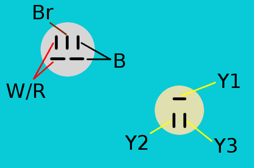
| Probe Connections |
W/R -Y1 | W/R-Y2 | W/R-Y3 |
| B-Y1 | B-Y2 | B-Y3 |
Regulator/Rectifier Circuit Check
To check the regulator/rectifier circuit a 12 V 3 ~ 6 W test light with wire leads and three 12 V batteries.
Step 1
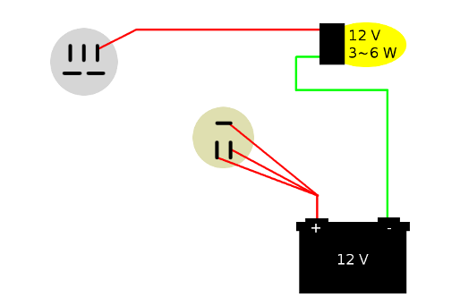
Connect the battery and test light to the regulator/rectifier terminals. Repeat the test with all three yellow wires of the 3-pin connector as indicated. The test light shouldn’t light. If the light is illuminated the regulator/rectifier should be replaced.
Step 2
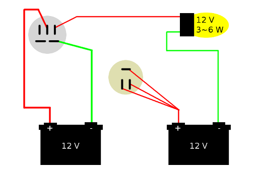
Set up a second 12V battery. Test the regulator as in the first test. The bulb should not light. If the light turns on the regulator is defective.
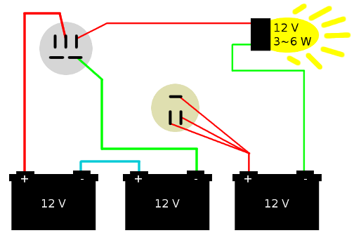
Set up a third 12V battery. Do not apply 24V to the brown wire terminal for more than a few seconds, and do not use more than 24 V. Test the regulator as in the first test.
The bulb should light. If the charging system components check out, but the system still doesn’t function correctly try replacing the regulator/rectifier with a known good unit.
Removal and Installation
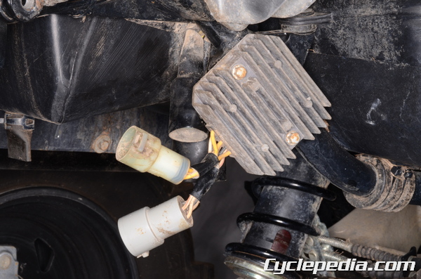
Unplug the two alternator connectors from the regulator rectifier. Remove the two mounting bolts with an 8 mm socket. and remove the regulator/rectifier.
Install the regulator/rectifier. Insert the two mounting bolts and tighten them to securely with an 8 mm socket. Plug in the two alternator connectors.