
 Like this Manual?
SAFETY FIRST: Protective gloves and eyewear are recommended at this point.
Remove the CVT cover. See the CVT Cover topic.
Remove the drive pulley and belt. See the Drive Belt topic.

Hold the driven pulley with the special holder tool and loosen the driven pulley nut with a 27 mm socket.
Special Tools
Flywheel & Pulley Holder: 57001-1605
Pulley Holder Attachment: 57001-1472

Remove the driven pulley nut.

Remove the first driven pulley washer.

Remove the second driven pulley washer.

Remove the driven pulley from the driven shaft.
Disassembly

Secure the holder tool in a vise.
Special Tool – Drive and Driven Pulley Holder: 57001-1473

Set the driven pulley onto the special holder tool.
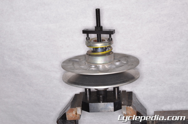
Install the spring holder set to the driven pulley. Thread the guide bar into the pulley holder tool. Tighten spring holder nut with a wrench to compress the spring.
Special Tool – Spring Holder Set: 57001-1483

Compress the spring until there is easy access to the snap ring.
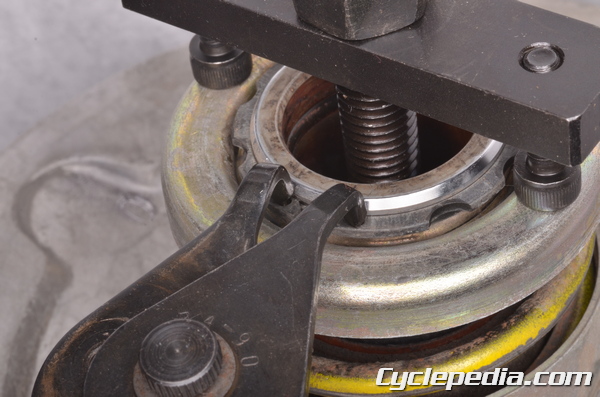
Spread the snap ring with snap ring pliers and free it from the groove.
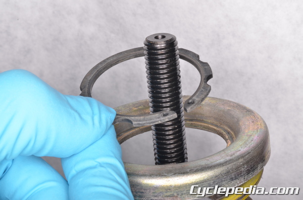
Remove the ease off the spring holder pressure and remove the spring holder bar. Remove the snap ring.

Remove the outer spring seat.

Remove the driven pulley spring.

Lift off the inner driven pulley spring seat.

Remove the thrust plate.


Note the positions of the fixed and movable faces (sheaves) of the driven pulley. Place a paint mark on the backs of the pulleys so that they can be returned to their original positions on assembly.

Clean away any molybdenum grease from the inside of the driven pulley shaft.

There are four pins that hold the movable face to the fixed face of the driven pulley. Lift up on the pins with a small flat blade screwdriver.

Remove the four pins.

Lift the movable face off of the shaft on the fixed driven face.

Remove the spacer/s from the base of the fixed driven face shaft.
Inspection

Inspect the faces of the driven pulley for signs of oil/grease contamination, wear, and damage. Clean the driven faces with an oil free solvent.

Check the faces against a straight edge and make sure there is no uneven wear. Replace the faces if there are any inconsistencies with surface of the faces.

Measure the free length of the spring. Replace the spring as needed.
Spring Free Length: 99.5 mm (3.92 in.)

Inspect the bushings in the movable driven face. Measure the inside diameter of the bushings. Replace the movable driven face if the bushings are in poor condition.
Movable Driven Face Bushing Inside Diameter: 40.000 ~ 40.039 mm (1.5748 ~ 1.5763 in.)
Service Limit: 40.07 mm (1.578 in.)

Inspect the splines of the fixed driven face. Replace the fixed driven face as needed.

Inspect the two oil seals in the movable driven face. Replace the oil seals as needed.

Inspect the condition of the driven pulley O-rings and replace them as needed.
Assembly
Take care to avoid contaminating the faces of the driven pulley with grease or oil.

Apply molybdenum disulfide grease to the O-rings, pins, and the bushings.
Install the spacer/s. If installing multiple spacers install the thicker spacer on the movable driven face side and the thinner spacer on the fixed driven face side. For more information about spacer selection see the Belt Inspection topic.
Note the locations of the paint marks on the movable and fixed drive faces.
Fit the movable drive face onto the fixed drive face so that they are in their original positions.
Install the pins to hold the two faces together. Apply grease to the pin openings. Do not have excessive clumps of grease.
Secure the holder tool in a vise.
Special Tool – Drive and Driven Pulley Holder: 57001-1473
Set the driven pulley onto the special holder tool.
Install the thrust plate. Install the inner spring seat onto the driven pulley.
Thread the spring holder guide bar into the holder tool and set the spring in place.
Special Tool- Spring Holder Set: 57001-1483
Install the outer spring seat over the top of the spring. Set the snap ring over the guide bar.
Install the spring holder set to the driven pulley. Tighten the spring holder nut with a wrench to compress the spring.
Compress the spring until the snap ring groove is visible. Install the snap ring into its groove with snap ring pliers.
Make sure the snap ring is secure in its groove and back off the spring compressor tool. Remove the spring tool.
Installation
Fit the driven pulley onto the driven shaft. Make sure to align the splines of the pulley with the splines of the shaft.
Place the two washers on the driven shaft so that the concave side of the washers face towards the driven pulley.
Thread on the driven pulley nut. Hold the driven pulley with the special holder tool and torque the driven pulley nut to specification with a 27 mm socket.
Driven Pulley Nut: 93 N-m, 9.5 kgf-m, 69 ft-lb
Special Tools
Flywheel & Pulley Holder: 57001-1605
Pulley Holder Attachment: 57001-1472
Install the drive pulley and belt. See the Drive Belt topic.
Install the CVT cover. See the CVT Cover topic.