
 Like this Manual?
SAFETY FIRST: Protective gloves and eyewear are recommended at this point.
Remove the differential. See the Front Differential topic for more information.
Remove the 2WD / 4WD actuator. See the Actuators topic for more information.
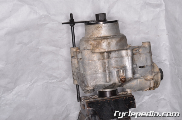
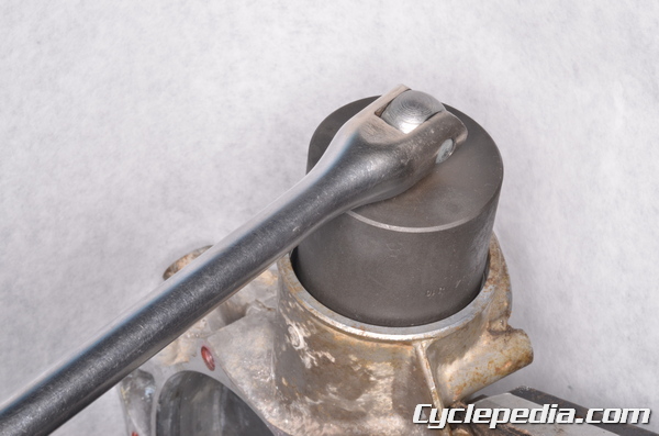
Support the front differential in a vise with the special tools.
Special Tool – Gear Holder and Socket Wrench Hex 24: 57001-1489
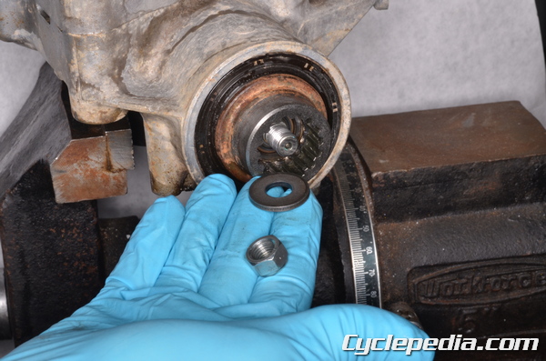
Loosen the front differential coupling nut with a 14 mm socket. Remove the coupling nut and washer.
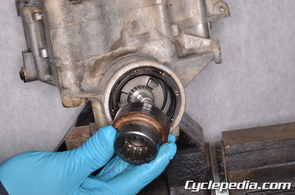
Remove the coupling piece.
Remove the 2WD / 4WD shifter.
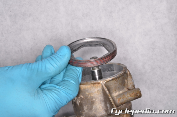
Remove the coupling oil seal.
There are eight left differential cover bolts.
Remove the left differential cover bolts with an 8 mm socket.
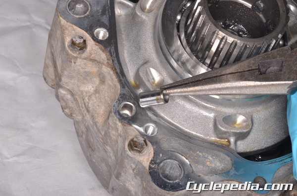
Utilize the pry points and a pry bar to free the left differential cover.
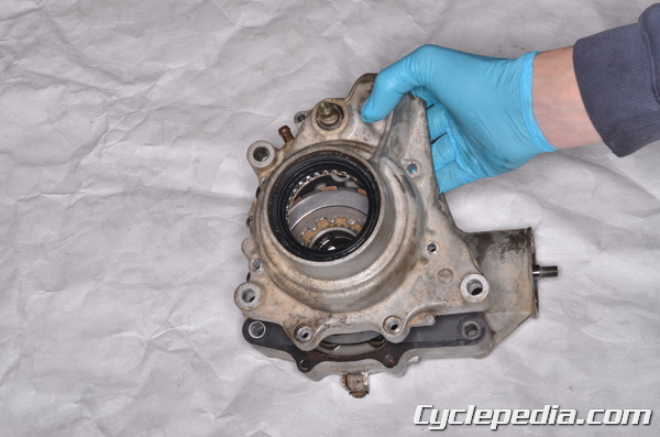
Remove the left differential cover.
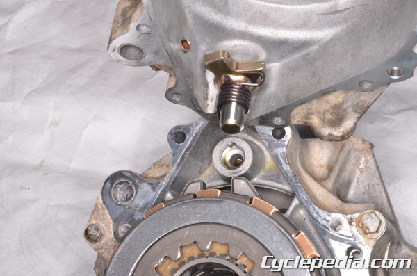
The variable differential control shift shaft and spring should come out with the cover.
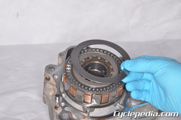
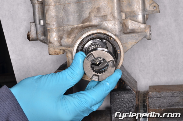
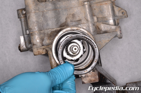
Remove the outer disc.
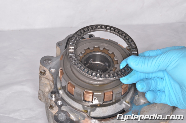
Remove the outer needle bearing.
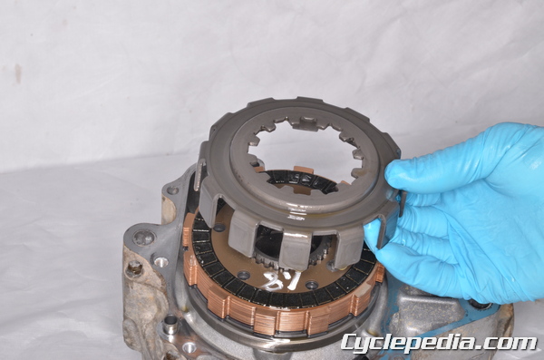
Lift off the differential disc basket.
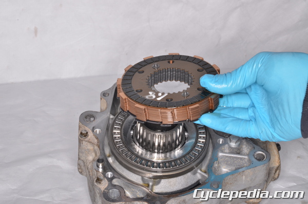
Lift off the differential disc clutch pack.
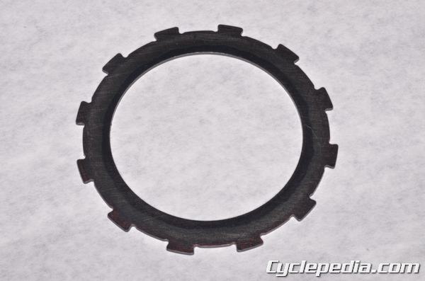
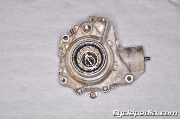
The inner disc is in from the rest.
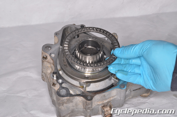
Remove the inner needle bearing.
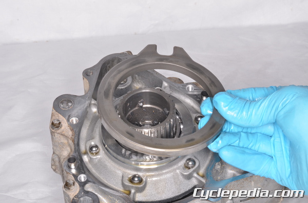
Remove the cam plate to reveal the six steel balls.
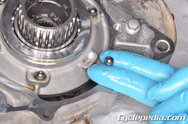
Remove the six steel balls.
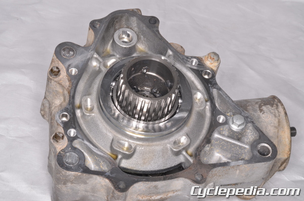
Remove the differential left cover gasket and dowel pins.
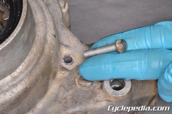
There are four front differential case bolts.
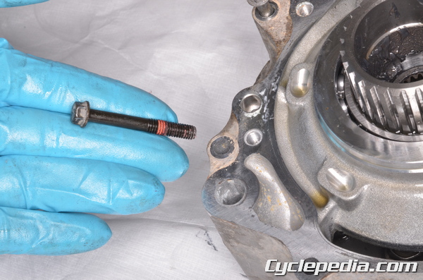
Remove the two M6 bolts with an 8 mm socket.
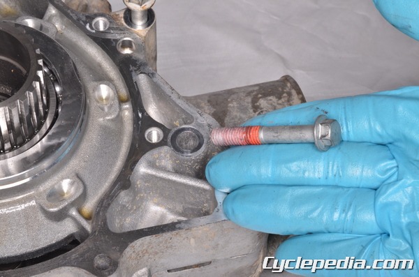
Remove the two M8 bolts with a 10 mm socket.
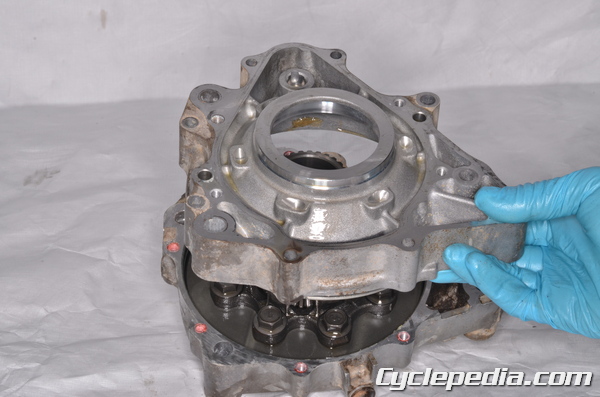
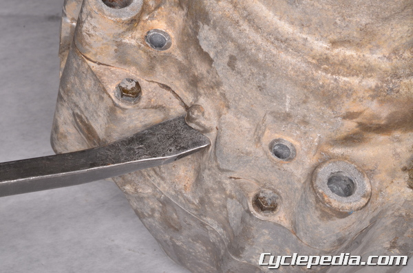
Separate the differential case halves.
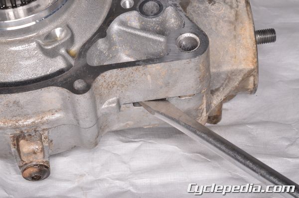
Utilize the pry points as needed.
Lift off the ring gear left shim/s.
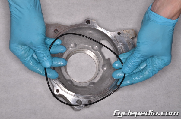
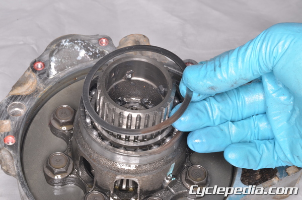
Remove the differential case O-ring and discard it.
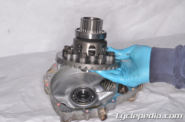
Lift out the ring gear assembly.
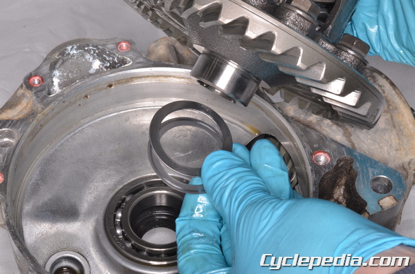
Remove the right ring gear shim/s.
To remove the pinion gear the bearing holder secure the right differential case in a soft jawed vise. Use the special socket wrench to loosen the pinion gear bearing holder. Apply heat to the area around the bearing holder to free the thread locking agent.
Special Tool – Socket Wrench Hex 41: 57001-1484
Remove the pinion gear bearing holder.
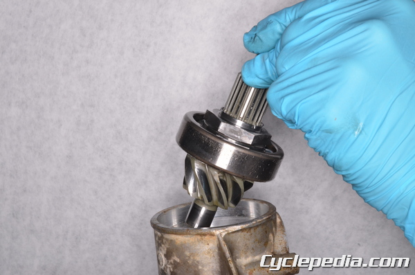
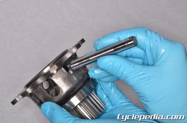
Lift out the pinion gear and bearing.

Remove the pinion gear shim/s.
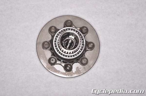
The spider gear case is held to the ring gear with eight bolts.
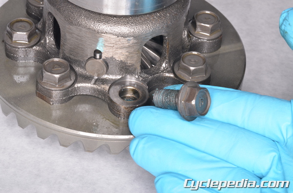
Remove the ring gear bolts with a 14 mm socket.
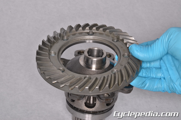
Remove the ring gear.
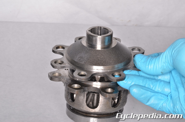
Remove the spider gear case cover.
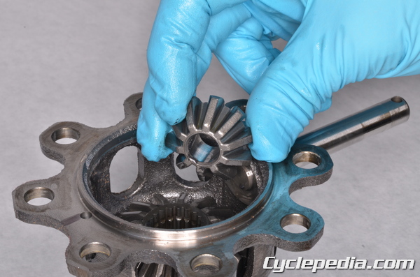
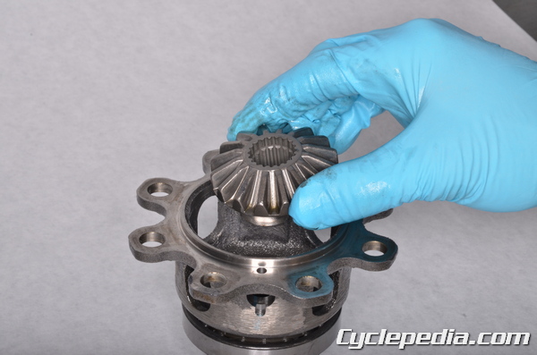
Remove the right side gear (16T).
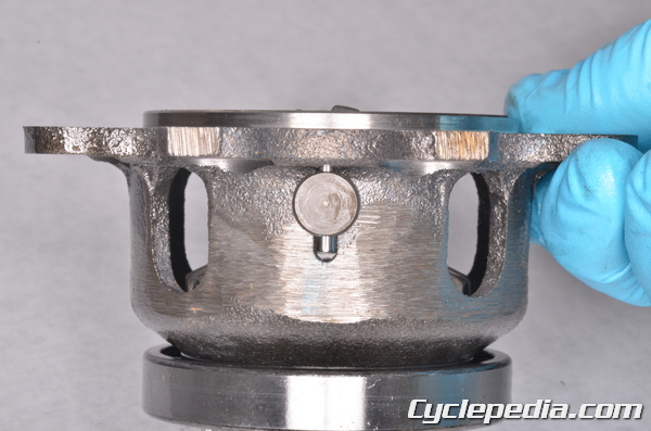
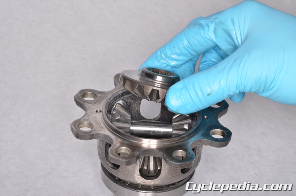
The spider gear shaft is held in the spider gear case by two pins.
Remove the spider gear shaft pins.
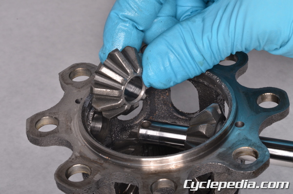
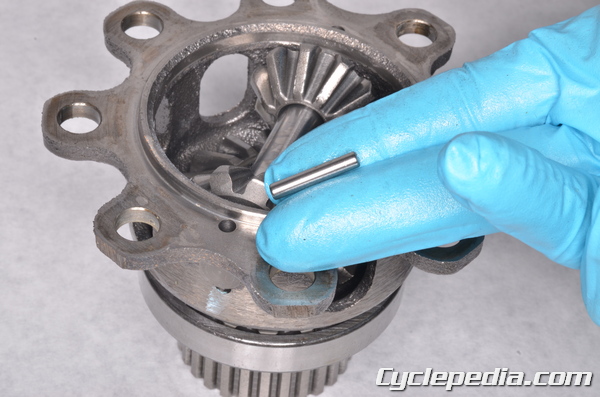
Push out the spider gear shaft and remove the spider gears (10T).
Remove the spider gear shaft.
Remove the left side gear (16T).
Inspection
See the Differential Inspection topic for more information.
Assembly
See the Differential Assembly topic for more information.
Installation
See the Front Differential topic for more information.