
 Like this Manual?
SAFETY FIRST: Protective gloves and eyewear are recommended at this point.
Removal

Remove the cylinder head covers and cam chain tensioners. See the Cylinder Head Covers topic for more information.

Lift the camshafts out of the cylinder heads.

Secure the cam chains with a length of wire to keep the cam chains from falling into the crankcase.
Inspection
To inspect the rocker arms see the Rocker Arms topic.

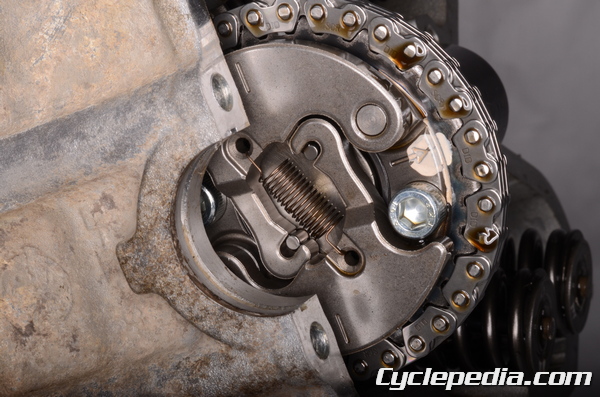
The Kawasaki Automatic Compression Release (KACR) system reduces engine compression at low rpm to aid in starting. The system works by having two weights that swing out at high engine speed and retract the pusher piece that opens the exhaust valves early.

Make sure the weights open and close smoothly. When the camshaft is at rest the weights should be retracted.

When the weights are in the pin should be extended in the exhaust camshaft lobe. When the weights are moved out the pin should retract. This allows for full compression during normal engine running.

If the KACR system isn’t working properly only the weights and weight springs can be replaced. If the shaft and pin components are not working correctly the camshaft must be replaced.

Inspect the camshaft for wear and damage.

Measure the height of the cam lobes at their largest points with a micrometer or Vernier calipers. Replace the camshaft as needed.
Exhaust Cam Height
2002 – 2003 and 700: 35.363 – 35.477 mm (1.3932 – 1.3967 in.)
Service Limit: 35.26 mm (1.388 in.)
2005 – 2011: 35.245 – 35.594 mm (1.3876 – 1.4013 in.)
Service Limit: 35.15 mm (1.384 in.)
Intake Cam Height: 35.622 – 35.736 mm (1.4024 – 1.4069 in.)
Service Limit: 35.52 mm (1.398 in.)

Use Plastigauge to check the camshaft journal oil clearance. Place the Plastigauge over the camshaft journals. Install the cylinder head covers one at time without sealant. See the Rocker Arms topic for more information.

Remove the cylinder head cover and check the Plastigauge according to its clearance chart. Measure at the widest section of the Plastigauge for an accurate measurement. If the measurement is over the service limit proceed to the next inspection, otherwise measure the camshaft runout.
Note: Do not rotate the camshaft during the procedure or use bonding agent on cylinder head cover.
Camshaft Bearing Clearance
@ Diameter 18: 0.016 – 0.052 mm (0.0006 – 0.0020 in.)
Service Limit: 0.14 mm (0.0055 in)
@ Diameter 22: 0.020 – 0.062 mm (0.0008 – 0.0024 in.)
Service Limit: 0.15 mm (0.0059 in.)
If the journal oil clearance is out of specification measure the diameter of the camshaft journals with a micrometer.
Camshaft Journal Diameter:
@ Diameter 18: 17.966 – 17.984 mm (0.7073 – 0.7080 in.)
Service Limit: 17.94 mm (0.706 in.)
@ Diameter 22: 21.959 – 21.980 mm (0.8645 – 0.8653 in.)
Service Limit: 21.93 mm (0.863 in.)
Replace the camshafts, cylinder head cover, and cylinder head as needed. The cylinder head and cylinder head cover must be replaced as a set.
Installation
Note: Make sure the engine timing is absolutely correct before running the engine.
Install the camshaft sprocket to the camshaft if it was removed. Fit the weight grooves around the pins and install the weight spring so that its open ends are facing towards the camshaft. Apply blue Loctite (non-permanent) to the threads of the camshaft sprocket bolts. Install the two camshaft sprocket bolts and tighten them to specification with a 5 mm Allen.
Camshaft Sprocket Bolts: 12 N-m, 1.2 kgf-m, 104 in-lb

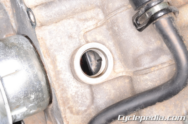
The camshafts must be installed in the correct position relative to the crankshaft. Support the cam chains when turning the crank and do not allow the cam chains to be pulled into the crankcase. Turn the crankshaft clockwise with a 19 mm socket until the rear piston is at TDC.

The rear piston will be at TDC when the “T-R” mark is aligned with the indicator in the timing hole. Make sure the crank stays at this position during the installation of the rear camshaft or the timing will not be correct.
Fit the rear camshaft into its cylinder head with its lobes facing down.

The arrow on the camshaft sprocket must be facing up, and the lines on the weights should be level with the cylinder head-to-cylinder head cover mating surface.
When the rear cylinder head cover is to be installed have the rear camshaft in this position. See the Cylinder Head Covers topic for more information.
From the “T-R” mark turn the crankshaft 270° clockwise till the “T-F” mark shows.

Fit the front camshaft into its cylinder head with its lobes facing down.
The arrow on the camshaft sprocket must be facing up, and the lines on the weights should be level with the cylinder head-to-cylinder head cover mating surface.
When the front cylinder head cover is to be installed have the front camshaft in this position. See the Cylinder Head Covers topic for more information.