
 Like this Manual?
SAFETY FIRST: Protective gloves and eyewear are recommended at this point.
Removal
Remove the rear shock absorber. See the Rear Shock Absorber topic for more information.
Remove the rear axle. See the Rear Axle topic for more information.

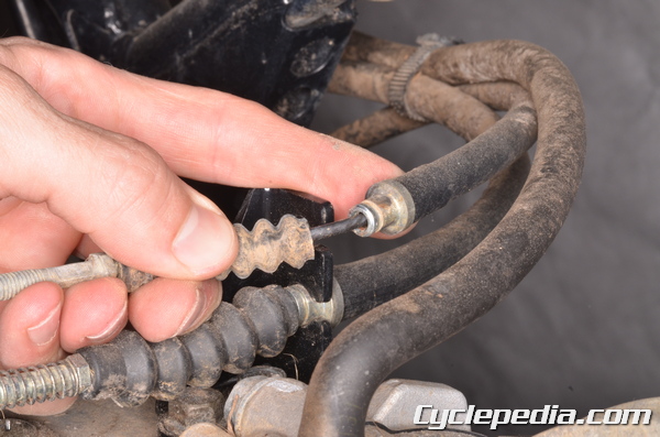
Locate the rear brake adjuster.
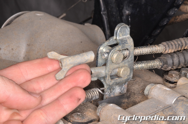
Loosen and remove the rear brake adjuster wing nuts.
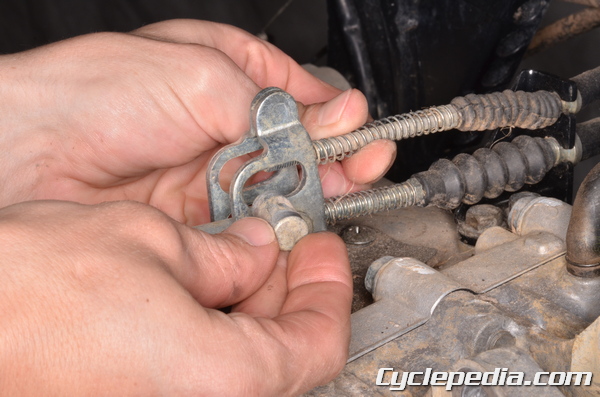
Pull the cables back and remove the cable joints.
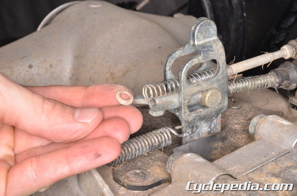
Remove the rear brake cable spring seats.
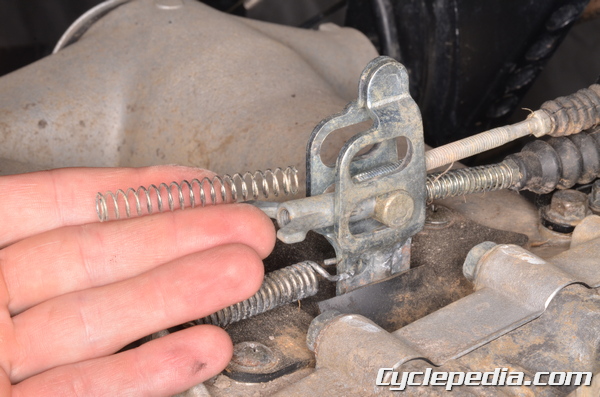
Remove the springs.
Slide the rubber cover forward and free the rear brake cables from the bracket.
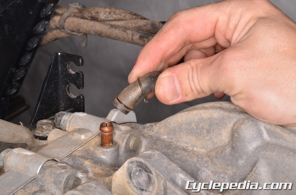
Pull back the clamp and free the vent hose from the final gear case.
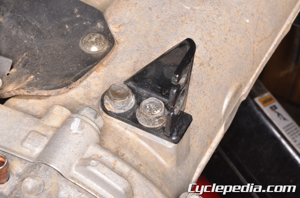
Remove the two rear brake cable bracket bolts using a 12 mm socket. Remove the rear brake cable bracket.
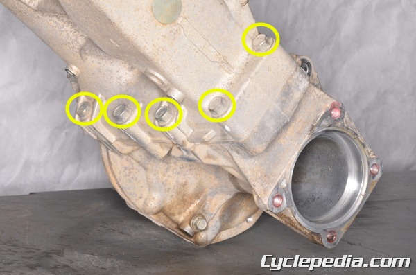
There are 10 final gear case bolts.
Remove the final gear case bolts with a 14 mm socket.
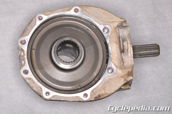
Free the final gear case from the swingarm.
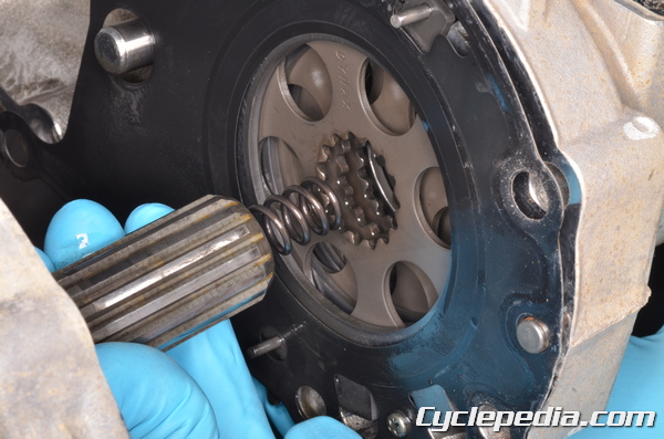
Guide the pinion gear shaft out of the we brake assembly.
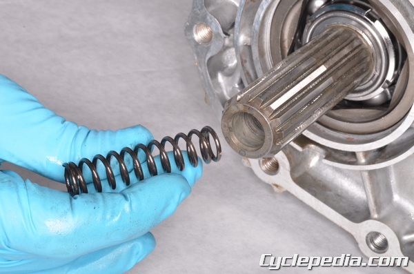
Remove the spring from the pinion gear shaft.
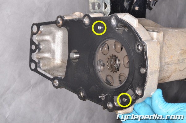
There are two screws that hold the gasket to the swingarm.
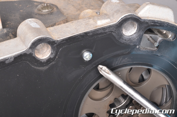
Remove the two gasket screws with a Phillips screwdriver.
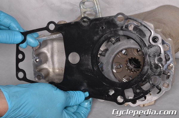
Remove the old gasket and discard it. Remove the two dowel pins.
Disassembly
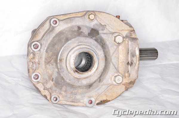
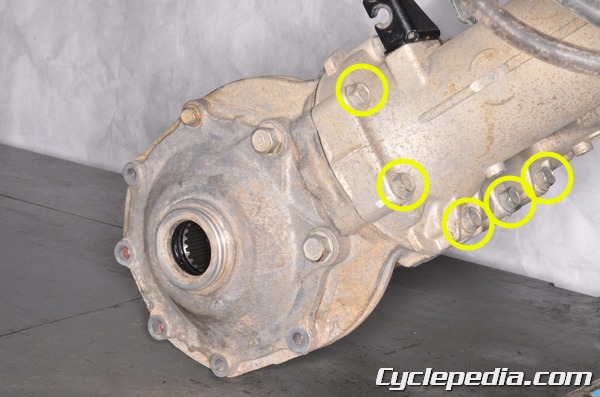
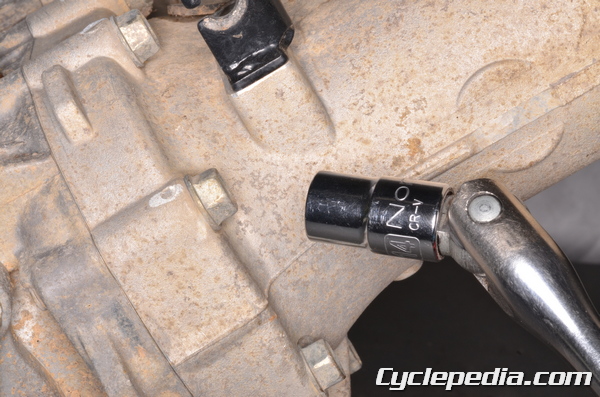
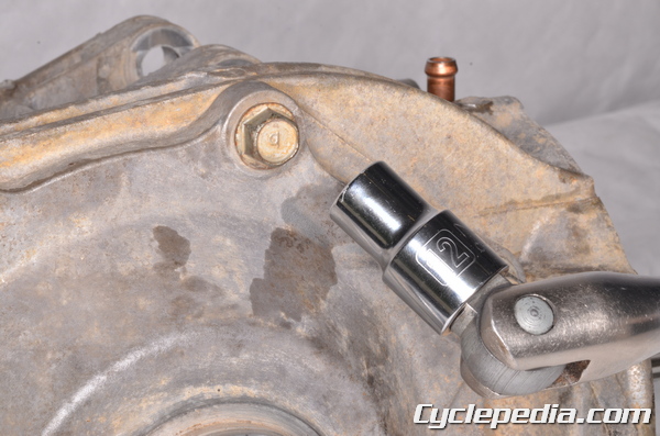
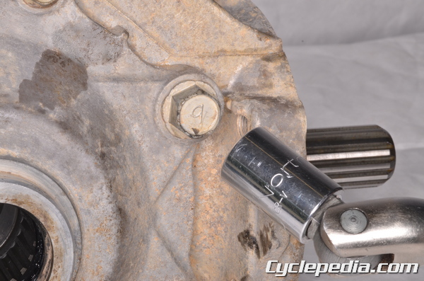
Remove the right final gear case cover bolts using a 12 mm socket on the smaller bolt and a 14 mm socket on the two larger bolts.
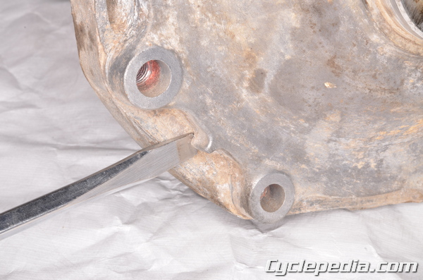
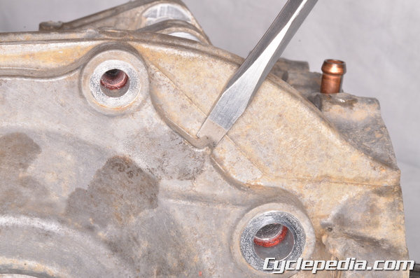
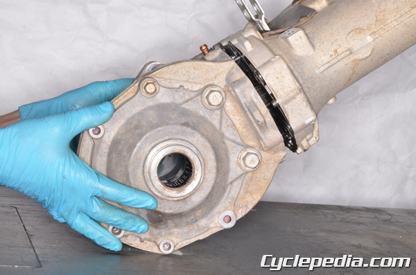
Utilize the pry pints to free the right final gear case cover.
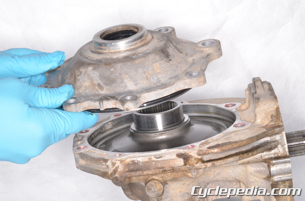
Remove the cover.
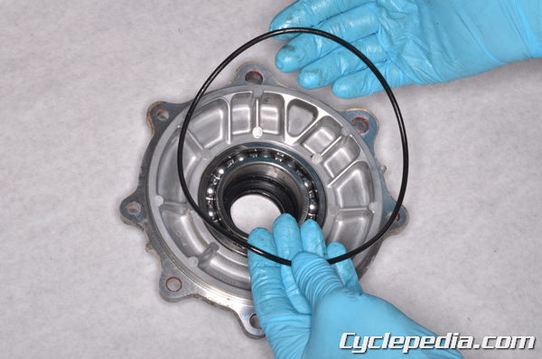
Inspect the O-ring and replace it as needed.
Remove the shim(s) from the final gear case.
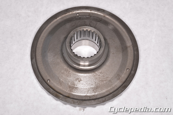
Remove the ring gear from the final gear case.
Support the final gear case in a vise so that the pinion shaft is pointing up.
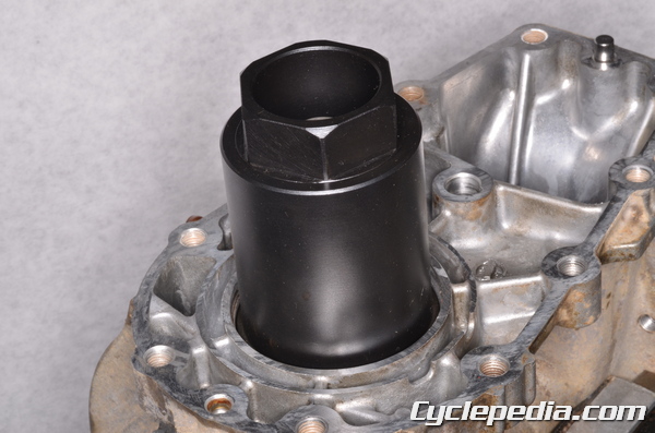
Loosen the pinion gear bearing holder nut with the special socket wrench. Heat the area around the holder nut if needed to free the thread locking agent.
Special Tool – Socket Wrench Hex 50: 57001-1478
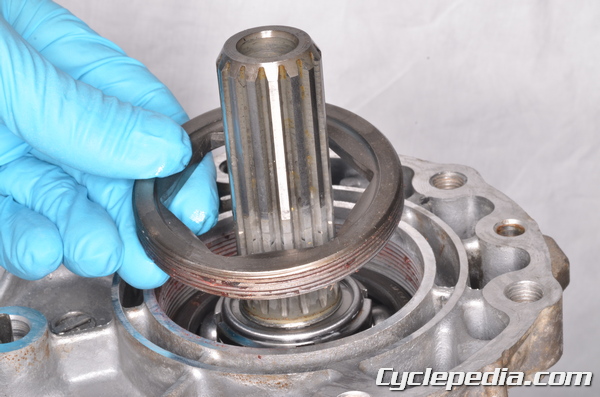
Remove the pinion gear bearing holder nut.
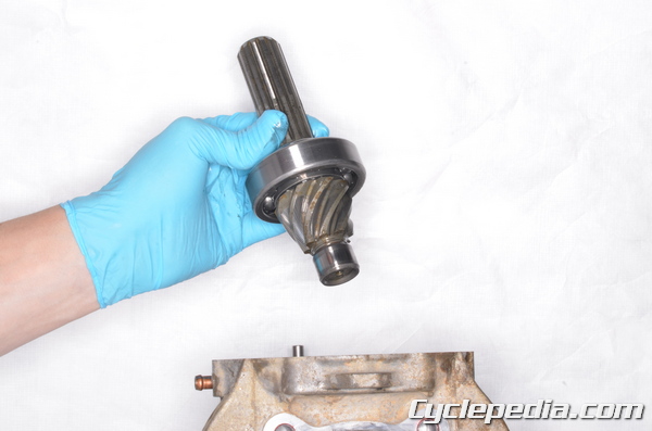
Lift out the pinion gear shaft with the bearing.
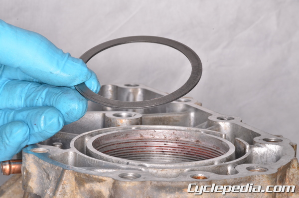
Lift out the shim(s).
Inspection
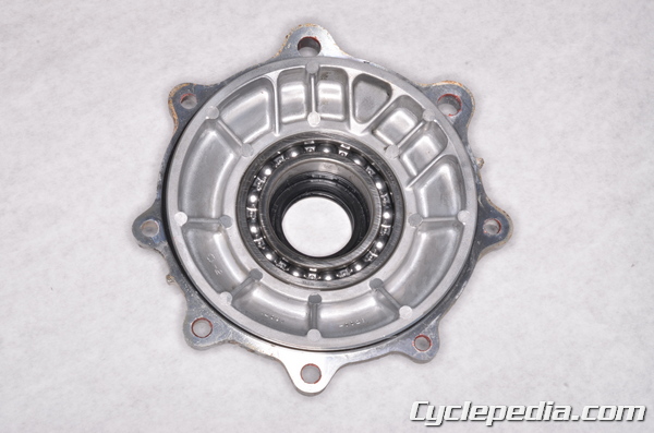
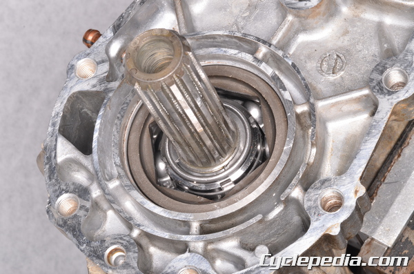
Inspect the right final gear case bearing by turning it by hand. Inspect the dual oil seals. Replace the parts as needed.
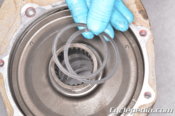
Drive in the new seals from the inside of the cover. Both seals have a C shaped cross-section. Position the seals so that the closed end of the C faces the other seal. Use a suitable driver that is the same outside diameter as the seal. Drive in the smaller diameter seal first. The inside edge of the smaller diameter seal must sit 44.8 – 45.8 mm (1.76 – 1.80 in.) below the inside surface of the cover. Drive in the larger diameter seal so that it is flush with its step.
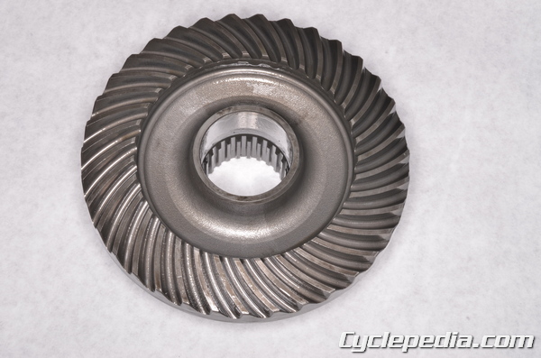
Inspect the teeth and splines of the ring gear for damage and wear. The pinion and ring gears must be replaced as a set.
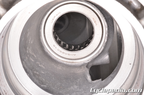
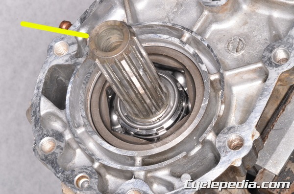
Inspect the pinion gear needle bearing by turning it by hand. If the bearing is in poor condition the final gear case must be replaced as a whole.
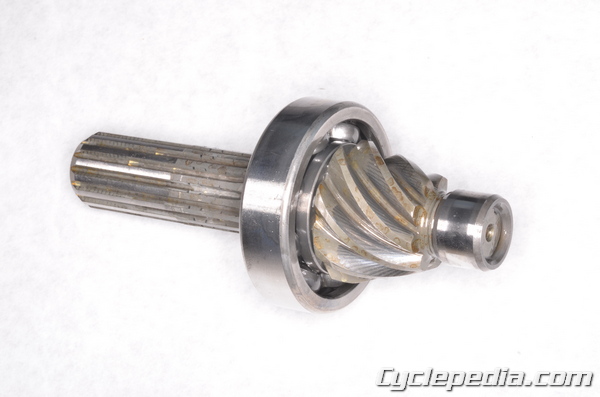
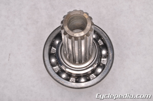
Inspect the pinion gear, shaft, and bearing. Turn the bearing by hand and make sure it turns smoothly.
To replace the pinion gear remove the nut with the special tools and then press the shaft out of the bearing.
Special Tools
Socket Wrench: 57001-1363
Pinion Gear Holder, m1.667: 57001-1363
Install the new bearing and press it on flush. Install the nut and use the special tools to tighten it to specification.
Pinion Gear Bearing Holder Nut: 157 N-m, 16 kgf-m, 116 ft-lb
Final Gear Adjustment
The ring and pinion gears must maintain correct backlash and tooth contact for performance and reliability. If the final gears are making noise the gear backlash/tooth contact may be out of specification.
Always check and adjust the backlash before the tooth contact.
The shims with the ring and pinion gears affect the amount of backlash and adjust the gear tooth contact. The shim/s with the pinion gear play a greater roll in setting the correct tooth contact, while the shim/s on the ring gear play a greater roll in setting the correct backlash.
Backlash
Backlash is the distance a gear will move back and forth without moving its mate gear.
Assemble the final gear case with a primary shim of 1.0 mm (0.039 in) thickness for each gear. Check the backlash as the final gear cover bolts are tightened. If the amount of backlash is reduced to zero stop tightening the cover bolts and swap the ring gear shim for a smaller size.
Assemble the final gear case with the rear axle and covers installed. See the Rear Axle topic for more information.
Support the final gear case with the pinion gear positioned above the axle (as if connected to the swingarm). Keep the rear axle from turning and affecting the measurement.
Place a dial gauge on the pinion gear shaft and turn the pinion gear shaft back and forth. Measure the amount of backlash between the pinion and ring gears.
Rear Final Bevel Gear Backlash (at pinion gear spline):
650 2002 – 2003 and 700: 0.07 – 0.14 mm (0.003 – 0.006 in.)
650 2005 – 2011: 0.04 – 0.20 mm (0.0016 – 0.0079 in.)
If the backlash is out of specification the shim/s must be adjusted.
Ring Gear Shims for Backlash Adjustment
Thickness | Part Number
0.15 mm (0.006 in.) | 92180-1417
0.2 mm (0.008 in.) | 92180-1418
0.5 mm (0.020 in.) | 92180-1419
0.8 mm (0.031 in.) | 92180-1420
1.0 mm (0.039 in.) | 92180-1421
1.2 mm (0.047 in.) | 92180-1422
To decrease the backlash increase the thickness of the ring gear shim/s. To increase the backlash decrease the thickness of the ring gear shim/s. Adjust the shim size a small amount at a time and recheck the backlash.
Tooth Contact
Set the backlash correctly before checking the tooth contact.
To check the gear tooth contact a special compound will be needed. The kind of compound used for checking automotive differential gears may be used. This can be found at many auto supply stores. Make sure the compound is smooth, firm, and around the consistency of tooth paste.
Thoroughly clean the teeth of the pinion and ring gears.
Apply the contact checking compound to the to 4 – 5 teeth on the pinion gear. Use a stiff bristle paint brush to apply the compound evenly. Do not use an excessive amount.
Assemble the final gear case. The backlash must be set correctly at this point or you are wasting your time.
Hold a gentle drag on the ring gear while turning the pinion gear shaft. Turn the pinion gear shaft 3 – 4 turns in the forward direction and the same in the reverse/coast direction.
Remove the gears and inspect the markings made by the compound. The compound will show where the teeth contact each other. The teeth should show contact centered on the face of the tooth slightly towards the toe (narrow end) of the tooth.
If the contact is far out of center the shim/s need to be changed. Change the shim/s a small amount at a time and recheck the tooth contact and backlash. Clean the checking compound from the teeth before each inspection.
Pinion Gear Shims for Tooth Contact Adjustment
Thickness | Part Number
0.15 mm (0.006 in.) | 92180-1423
0.2 mm (0.008 in.) | 92180-1424
0.5 mm (0.020 in.) | 92180-1425
0.8 mm (0.031 in.) | 92180-1426
1.0 mm (0.039 in.) | 92180-1427
1.2 mm (0.047 in.) | 92180-1428
Double check the gear backlash after the tooth contact has been set correctly. The backlash must remain in specification.
Assembly
Clean the final drive gear case components with a high flash point solvent and compressed air.
NOTE: Always wear safety glasses when using compressed air and never point it directly at yourself or anyone else.
Install the shim(s) into the final gear case.
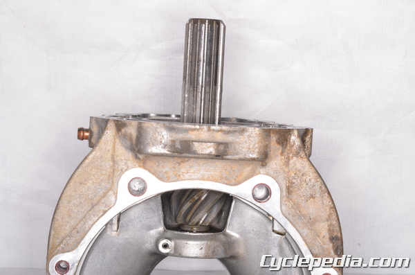
Install the pinion gear into the final gear case.
Apply a non-permanent thread locking agent (Blue Loctite) to the threads of the bearing holder nut. Do not contaminate the bearing with the locking agent.
Install the bearing holder nut and tighten it to specification with the special socket wrench.
Special Tool – Socket Wrench Hex 50: 57001-1478
Pinion Gear Bearing Holder: 137 N-m, 14 kgf-m, 101 ft-lb
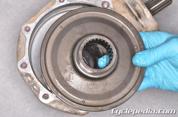
Install the O-ring to the right final gear case cover. Coat the O-ring and the dual oil seals in lithium based grease.
Install the ring gear into the final gear case. Install the shim(s) onto the ring gear boss.
Fit the right final gear case cover onto the final gear case. The right gear case bolts are also used for the trailer hitch bracket if equipped and/or the under cover. Coat the threads of the right final gear case cover bolts in a non-permanent thread locking agent (Blue Loctite).
Install the (M8) right final gear case cover bolts and tighten them to specification with a 12 mm socket.
Rear Final Gear Case Right Cover Bolts (M8): 24 N-m, 2.4 kgf-m, 17 ft-lb
Install the (M10) or (M12) right final gear case cover bolts and tighten them to specification.
Rear Final Gear Case Right Cover Bolts
2002 – 2003 (M10): 49 N-m, 5.0 kgf-m, 36 ft-lb
2005 – 2011, 700cc (M12): 93 N-m, 9.5 kgf-m, 69 ft-lb
Installation
Install the rear axle into the final gear case. See the Rear Axle topic for more information.
Install the two down pins. Install a new gasket.
Apply a non-permanent thread locking agent (Blue Loctite) to the threads of the gasket screws. Install the two gasket screws and tighten them securely with a Phillips screwdriver.
Install the spring into the pinion gear shaft.
Make sure the spring stays in place while fitting the final gear case to the swingarm.
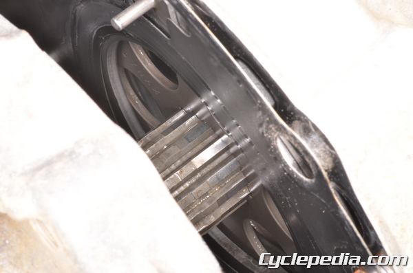
Fit the final gear case to the swingarm. Turn the rear axle to align the splines of the pinion gear shaft with the wet brake plates.
Install the 10 final gear case mounting bolts.
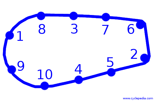
Tighten the bolts evenly to specification in the order given.
Rear Final Gear Case Bolts: 42 N-m, 4.3 kgf-m, 31 ft-lb
Install the brake cable bracket to the swingarm. Install the two mounting bolts and tighten them securely using a 12 mm socket.
Connect the vent hose to the final gear case and secure the hose with the clamp.
Fit the rear brake cables into the bracket.
Place the springs and spring seats on the rear brake cables.
Fit the brake cables through the joints and thread on the wing nuts.
Install the rear axle if it is not in place. See the Rear Axle topic for more information.
Install the rear shock absorber. See the Rear Shock Absorber topic for more information.
Adjust the rear brake. See the Brake Inspection topic for more information.