
 Like this Manual?
SAFETY FIRST: Protective gloves and eyewear are recommended at this point.
Removal
Remove the cylinder head. See the Cylinder Heads topic for more information.
Note the location of all of the valve parts so that they can be returned to their original positions. Remove all of the valves in the same manner.
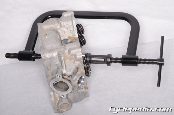
Use a valve spring compressor to remove the valves.
Special Tools
Valve Spring Compressor: 57001-241
Adapter, Ø22: 57001-1202
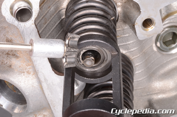
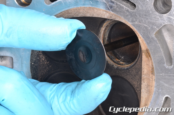
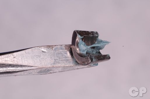
Compress the valve springs only enough to remove the split keepers. Remove the split keepers from the valve stem with tweezers or a magnet.
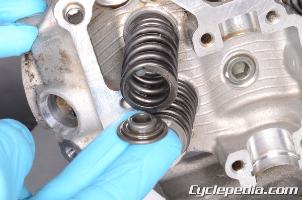
Remove the spring retainers.
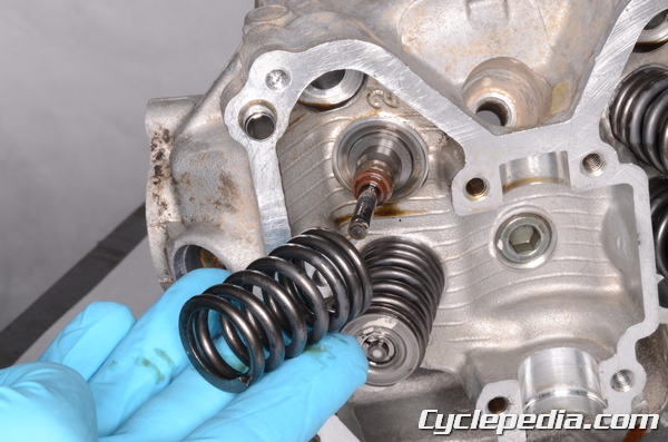
Lift out the valve spring.
Push the valves out through the bottom of the cylinder head.
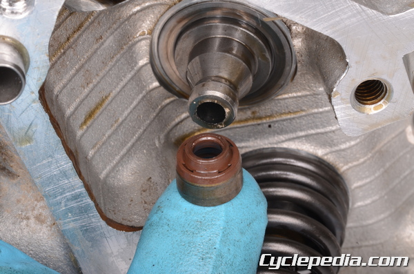
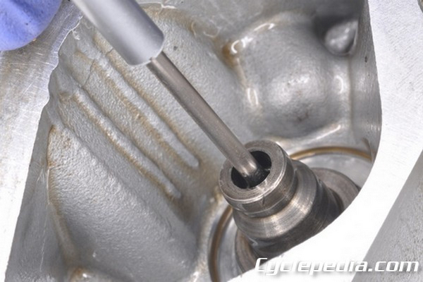
Remove the stem seals with needle nose pliers and a pick. Discard the old stem seals. Take care to avoid damaging the valve lifter bore.
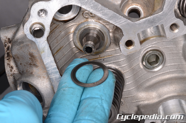
Remove the spring seats.
Inspection
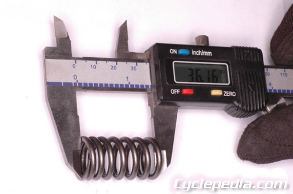
Measure the free length of the valve springs with vernier calipers. Replace the valve springs if they are below the service limit.
Valve Spring Free Length: 41.3 mm (1.626 in.)
Service Limit: 39.5 mm (1.555 in.)
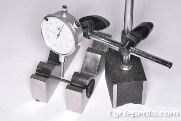
Use a set of V-blocks and dial gauge check the valve stem for bends. Replace the valves as needed.
Valve Stem Bend TIR Service Limit: 0.05 mm (0.002 in.)
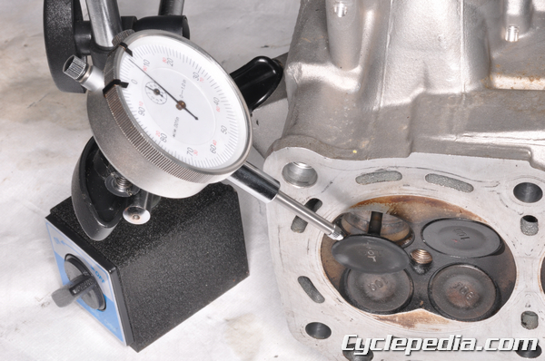
Lift the valve around 10 mm (0.39 in) from the cylinder head and check for valve stem deflection with a dial gauge and magnetic stand. If the deflection is out of specification inspect the valve and valve guide and replace the components as needed.
Valve/Valve Guide Clearance (Wobble Method):
Exhaust: 0.09 – 0.17 mm (0.0035 – 0.0067 in.)
Service Limit: 0.34 mm (0.0133 in.)
Inlet: 0.03 – 0.11 mm (0.0012 – 0.0043 in.)
Service Limit: 0.28 mm (0.0110 in.)
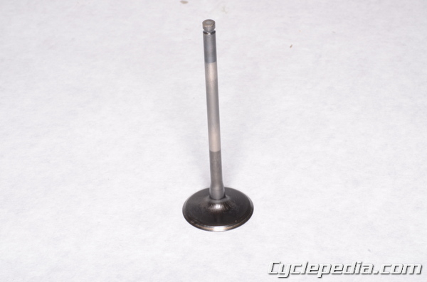
Inspect the valve for damage. Measure the valve stem diameter with a micrometer or vernier calipers and compare the measurements with specification. Replace any valves that do not meet the standard.
Valve Stem Diameter
Exhaust: 4.955 – 4.970 mm (0.1951 – 0.1957 in.)
Service Limit: 4.94 mm (0.1945 in.)
Inlet: 4.975 – 4.990 mm (0.1959 – 0.1965 in.)
Service Limit: 4.96 mm (0.1953 in.)
Measure the inside diameter of the valve guide with a small bore gauge.
Valve Guide Inside Diameter: 5.000 – 5.012 mm (0.1969 – 0.1973 in.)
Service Limit: 5.08 mm (0.20 in.)
Valve Guides
If you need to replace your valve guides we recommend taking your cylinder head to a qualified machine shop.
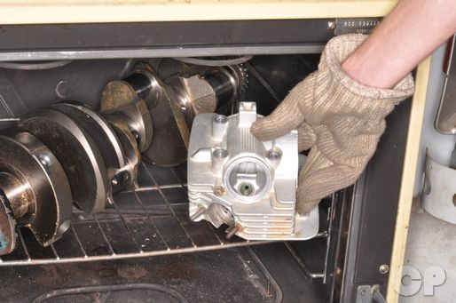
You will need to resurface the valve seats when you replace the guides. To remove the valve guides you must heat the area around the valve guide to 130° -140°C or 275° – 290°F with an oven. Do not use a torch because of the possibility of warping the head.
Gently hammer out the valve guide using a valve guide driver. Insert the driver through the valve opening and drive out the guide towards the top of the cylinder head. Be very careful to avoid damaging the cylinder head.
Special Tool- Valve Guide Arbor: 57001-1203
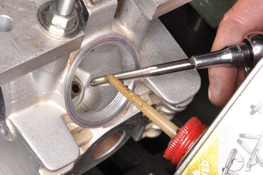
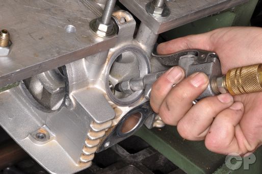
If a valve guide arbor is unavailable an alternate method can be used. Run a suitable sized tap into the valve guide from the top. Clean away any metal shavings with compressed air.
NOTE: Always wear safety glasses when using compressed air and never point it directly at yourself or anyone else.
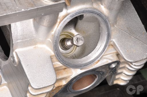
Thread a bolt into the recently tapped valve guide.
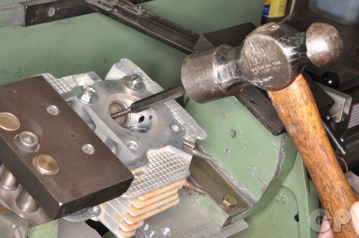
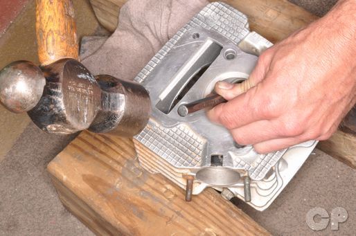
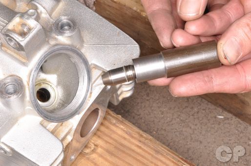
Insert a punch into the valve guide from the combustion chamber side.

Knock the valve guide out with a hammer.
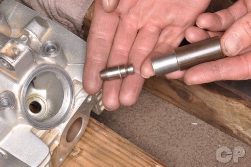
Install a new ring on the new valve guide.
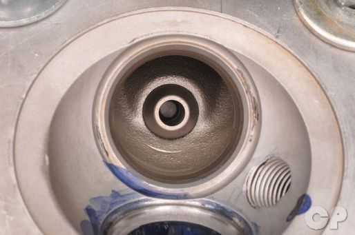
Lubricate the valve guide hole with fresh engine oil. Drive in the new valve guide with the special valve guide driver. Drive in the guides from the top of the cylinder head, and take care to avoid damaging the head. The flange on the valve guide should contact the cylinder head when the guide is installed.
Special Tool- Valve Guide Arbor: 57001-1203
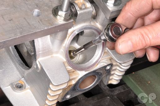
When the valve guides have been installed you must ream them to be ready to accept the valves. Use a valve guide reamer with cutting oil. Insert the reamer through the valve opening in the combustion chamber. Only turn the reamer clockwise. It is also necessary to ream the valve guides when installing a new valve.
Special Tool- Valve Guide Reamer: 57001-1204
Clean out the guide with compressed air and lubricate it with fresh engine oil.
NOTE: Always wear safety glasses when using compressed air and never point it directly at yourself or anyone else.
Valve Seat
We recommend taking your head to a machine shop if your valve seats need work.
The valve and guide must be in good condition to properly evaluate the seat.
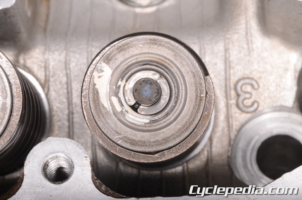
Coat the valve face with a thin layer of Prussian blue and install the valve into guide.
Using a valve lapping tool, spin the valve in a back and forth circular motion while applying downward pressure onto the valve.
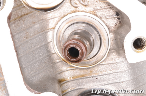
Pull the valve up and look for a complete impression of the Prussian blue all the way around valve seat. Measure the width of the valve seat and compare it to the specification. If there is a break in the compound on the seat or the width doesn’t meet the service limit, you will need to re-cut the valve seat.
Valve Seat Width: 0.5 – 1.0 mm (0.02 – 0.04 in.)
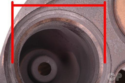
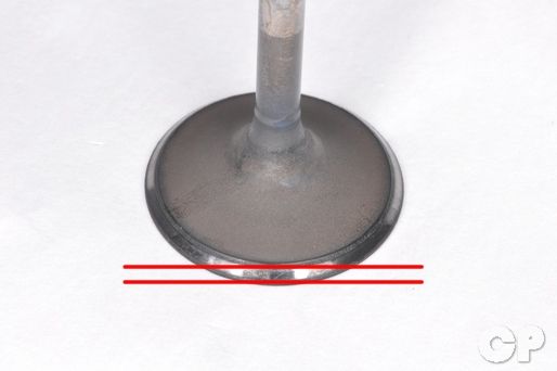
Measure the outside diameter of the valve seating surface (the area free of carbon buildup). If the measurements are out of specification or inconsistent around the circumference the valve seat must be repaired.
Valve Seat Outside Diameter
Exhaust: 25.2 – 25.4 mm (0.992 – 1.000 in.)
Inlet: 29.4 – 29.6 mm (1.157 – 1.165 in.)
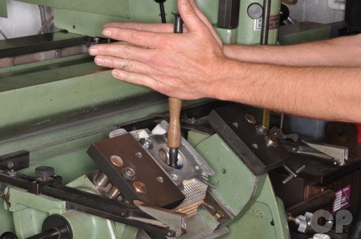
Valve Seat Cutting
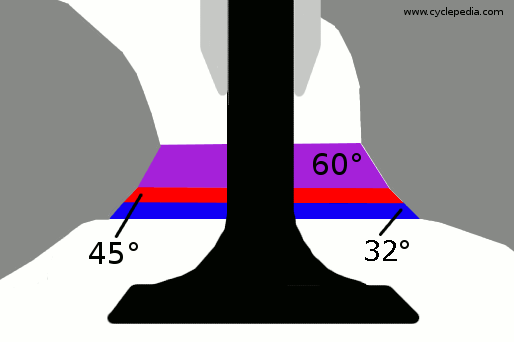
The valve seats have three different angle cuts to them by the special cutting tools. Use tool manufacturers instructions for cutting.
Special Tools
Valve seat Cutter Holder dia. 5 mm: 57001-1208
Valve seat Cutter Holder Bar: 57001-1128
Exhaust Valve Special Tools
Valve Seat Cutter 45°, dia. 27.5 mm: 57001-1114
Valve Seat Cutter 32°, dia. 28 mm: 57001-1119
Valve Seat Cutter 60°, dia. 30 mm: 57001-1123
Intake Valve Special Tools
Valve Seat Cutter 45°, dia. 30 mm: 57001-1187
Valve Seat Cutter 32°, dia. 33 mm: 57001-1199
Valve Seat Cutter 60°, dia. 30 mm: 57001-1123
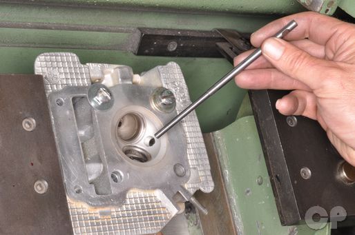
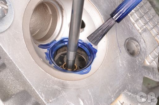
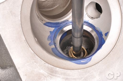
Install the pilot guide into the valve guide and rotate it 1/2 a turn while pushing it in.
Coat the valve seat in machinist dye so that it is easy to check your progress.
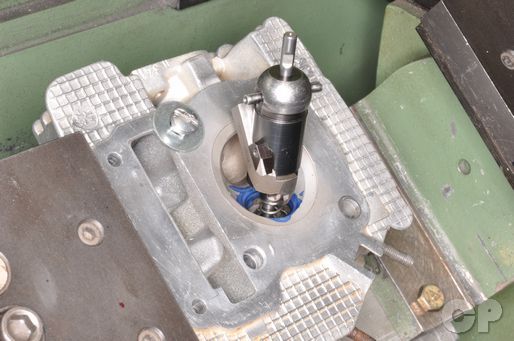
Install the 45° cutter onto the pilot making sure it fits snug.
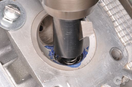
Rotate the cutter one to two times in a to clean up the seat.
NOTE: Cut only the minimum that you need and use light pressure.
Inspect the valve seat width above. If pitting is still evident repeat the process.
If the contact area on the exhaust is too wide (outside diameter) you will need to use the 32° cutter. This will help narrow and lower the fit of the valve to the seat.
Inspect the valve seat after each turn of the cutter.
If the contact area is too narrow (outside diameter) you will need to use the 60° cutter.
After making the other cuts, use the 45° degree cutter to clean up any imperfections or burrs that remain on the valve seat and bring the seating surface to the correct width.
Clean away the valve seat metal shavings with compressed air and washing oil.
Lap the valve with lapping compound mixed. Use light pressure, and do not allow the lapping compound to get into the valve guides. When you are finished thoroughly clean the lapping compound off of the cylinder head. Recheck the valve seat.
Assembly
Install the spring seats in their original locations.
Lubricate the new valve stem seals with fresh engine oil. Install new valve stem seals. Push the seals straight onto the guide.
Lightly coat the valve stem and end in moly solution. Insert the valve through the valve guide. Twist the valve slowly to work it through the stem seal without damaging the seal. The valve should move smoothly in the guide and make good contact with the seat.
Install the valve springs with the tightly would coils facing down. Install the spring retainers in their original locations.
Use a valve spring compressor to install the split keepers. Compress the valve springs only enough to install the split keepers
Special Tools
Valve Spring Compressor: 57001-241
Adapter, Ø22: 57001-1202
Apply grease to the inside of the split keepers. Apply a dab of grease to the end of a flat blade screwdriver. Set the keeper in the grease on the screwdriver and insert it onto the valve stem.
Repeat this with the other keeper. Slowly back off the spring compressor and make sure the split keepers hold
Special Tools
Valve Spring Compressor: 09916-14510
Attachment: 09916-14910
Tweezers: 09916-84511
After the valves have been reassemble place a clean shop towel under the cylinder head in the combustion chamber area. Make sure there is room for the valves to extend a bit. Gently tap each valve with a plastic rod and rubber mallet to make sure the valves are seated properly.
Support the cylinder head so that the intake port is facing up. Fill the port with gasoline, alcohol, or other suitable liquid to make sure the valves do not leak. Repeat the process with the exhaust valves.
Warning: Be extremely careful when handling gasoline.