
 Like this Manual?
SAFETY FIRST: Protective gloves and eyewear are recommended at this point.
Remove the bevel gear components. See the Bevel Gear topic for more information.
Visually inspect the bevel gear components for wear and damage.
Turn the shafts by hand and check the bearings for roughness and excessive play.
Bevel gear Adjustment
The bevel gears must maintain correct backlash and tooth contact for performance and reliability. Check the backlash and tooth contact if any of the gears or other backlash related components are replaced. If the bevel gears are making noise the gear backlash/tooth contact may be out of specification.
Always check and adjust the backlash before the tooth contact.
The shims on the drive and driven bevel gear housings affect the amount of backlash and adjust the gear tooth contact. The shim/s with the drive bevel gear housing play a greater roll in setting the correct tooth contact, while the shim/s on the driven bevel gear housing play a greater roll in setting the correct backlash.
Backlash
Backlash is the distance a gear will move back and forth without moving its mate gear.
Remove the output drive idle gear. See the Bevel Gear topic for more information.
Position a dial gauge on the shaft of the output drive bevel gear so its small movement can be measured. Hold the output shaft to keep it from moving and changing the measurement. Rotate the output drive bevel gear shaft back and forth to measure the amount of backlash between the two bevel gears.
Output Bevel Gear Backlash (at output drive shaft spline): 0.05 ~ 0.11 mm (0.0020 ~ 0.0043 in.)
Adjust the shim thickness gradually and recheck the backlash until it is in specification.
Driven Bevel Gear Shims for Backlash Adjustment
Thickness : Part Number
0.15 mm (0.006 in.): 92180-1307
0.2 mm (0.008 in.): 92180-1308
0.5 mm (0.020 in.): 92180-1309
0.8 mm (0.031 in.): 92180-1310
1.0 mm (0.039 in.): 92180-1349
1.2 mm (0.047 in.): 92180-1350
Tooth Contact
Set the backlash correctly before checking the tooth contact.
Remove the bevel gears. See the Bevel Gear topic for more information.
To check the gear tooth contact a special compound will be needed. The kind of compound used for checking automotive differential gears may be used. This can be found at many auto supply stores. Make sure the compound is smooth, firm, and around the consistency of tooth paste.
Thoroughly clean the teeth of the bevel gears.
Apply the contact checking compound to the to 4 – 5 teeth on the output driven bevel gear. Use a stiff bristle paint brush to apply the compound evenly. Do do not use an excessive amount.
Install the bevel gear housings into the crankcase. The backlash must be set correctly at this point or you are wasting your time.
Hold a gentle drag on the bevel drive gear shaft while turning the bevel driven gear shaft. Turn the bevel driven gear shaft 3 – 4 turns in the forward direction and the same in the reverse/coast direction.
Remove the bevel gears and inspect the markings made by the compound. The compound will show where the teeth contact each other. The teeth should show contact centered on the face of the tooth slightly towards the toe (narrow end) of the tooth.
If the contact is far out of center the shim/s need to be changed. Change the shim/s a small amount at a time and recheck the tooth contact and backlash. Clean the checking compound from the teeth before each inspection.
Drive Bevel Gear Shims for Tooth Contact Adjustment
Thickness : Part Number
0.15 mm (0.006 in.): 92180-1311
0.2 mm (0.008 in.): 92180-1312
0.5 mm (0.020 in.): 92180-1313
0.8 mm (0.031 in.): 92180-1314
1.0 mm (0.039 in.): 92180-1351
1.2 mm (0.047 in.): 92180-1352
Double check the gear backlash after the tooth contact has been set correctly. The backlash must remain in specification.
Output Drive Bevel Gear
Disassembly
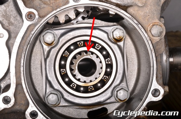
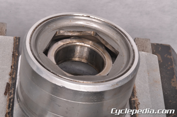
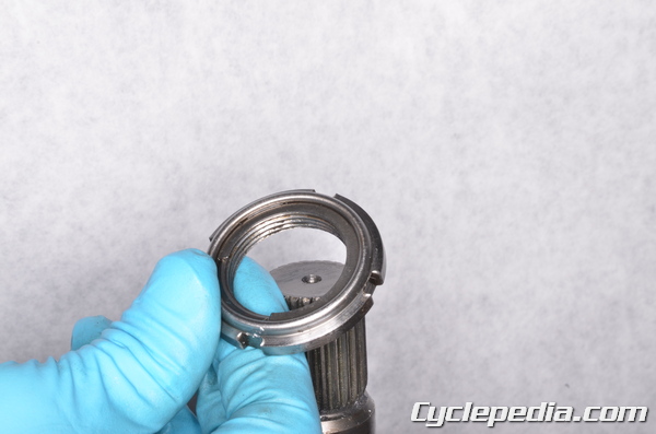
Turn the drive bevel gear until the grooves in the holder nut can be seen through the holes in the side of the housing. The holder nut has four grooves that should line up with the holes at the same time.
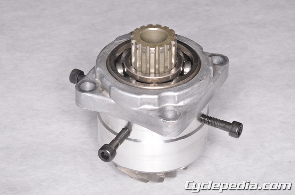
Insert the special holder bolts into the housing until the ends of the bolts fit into the grooves on the holder nut. When the bolts are installed correctly the gear and shaft will not be able to turn.
Special Tool – Nut Holding Bolts: 57001-1481
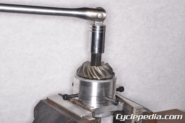
Hold the bevel gear housing in a soft jawed vise. Loosen the output bevel drive gear with a 17 mm Allen. After four rotations the holder nut will have moved beyond the reach of the holder bolts. You can remove one of the bolts and double check if this has happened.
Remove the holder bolts. Turn the shaft and check through the holes in the housing. If the holder grooves are not visible tap the shaft end of output drive bevel gear with a copper mallet. This will move the shaft and the holder nut up so the special holder bolts can be used again.
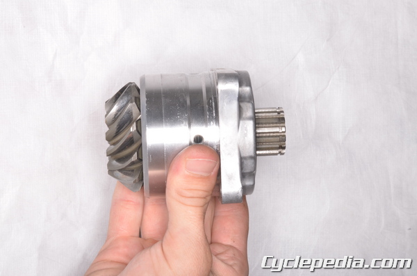
Continue loosening the holder nut in this manner until it is free from the shaft. The nut is free when it can be head clanking inside the housing when the holder bolts are removed.
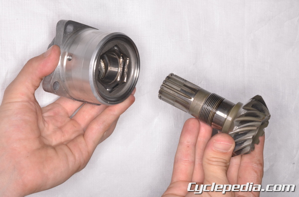
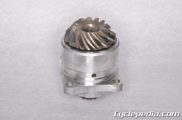
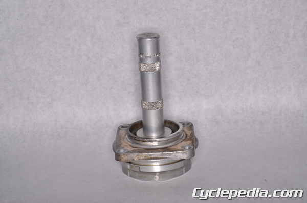
Remove the output bevel drive gear from the housing. Inspect the output bevel drive gear and shaft for wear and damage. Replace the shaft as needed.
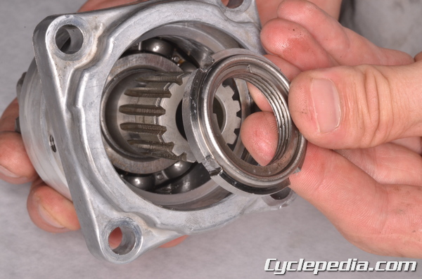
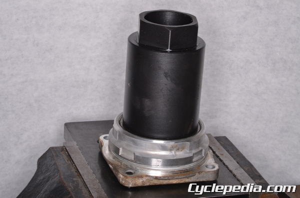
Hold the bevel gear housing in a soft jawed vise. Loosen the bearing holder with the special wrench. If needed heat the area around the holder to break loose the thread locking agent.
Special Tool – Hexagon Wrench, Hex 41: 57001-1491
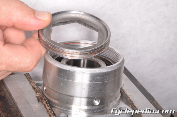
Remove the bearing holder.
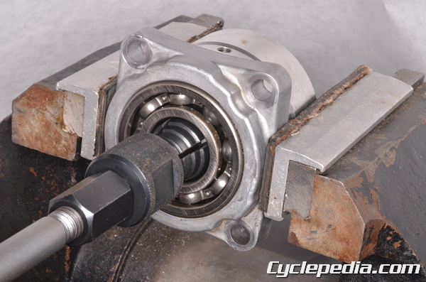
Remove the left side bearing with a suitable bearing puller.
Special Tool – Oil Seal and Bearing Remover: 57001-1058
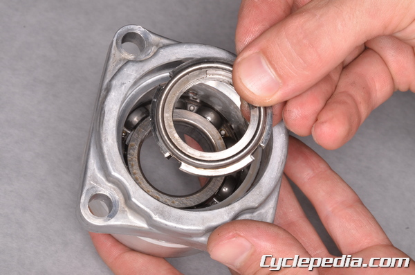
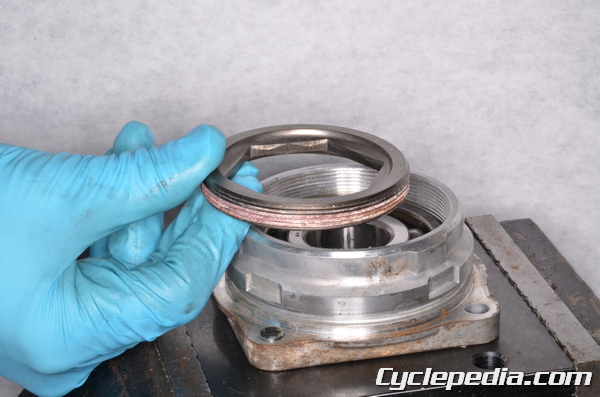
Remove the holder nut
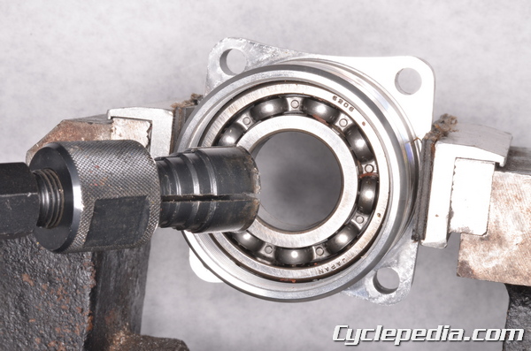
Remove the right side bearing with a suitable bearing puller.
Special Tool – Oil Seal and Bearing Remover: 57001-1058
Assembly
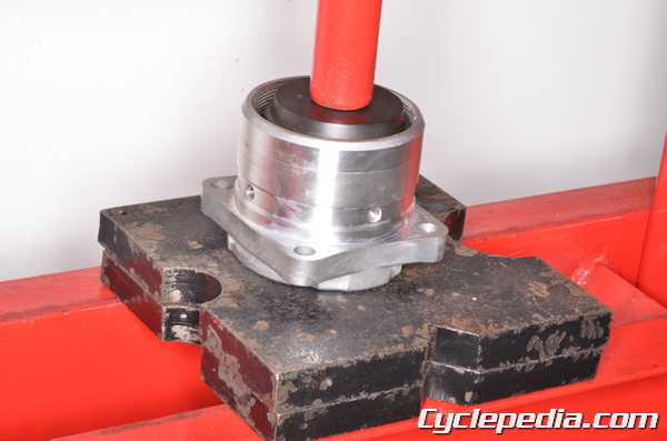
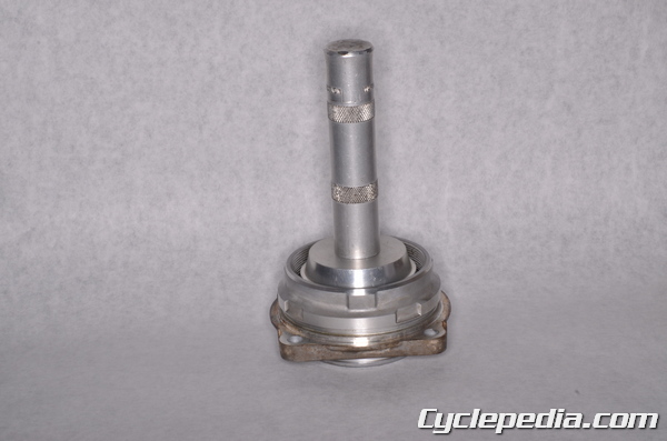
Drive in a new right side bearing with a suitable bearing driver that is the same outside diameter of the bearing’s outer race. Make sure the bearing is fully seated.
Special Tool – Bearing Driver Set: 57001-1058
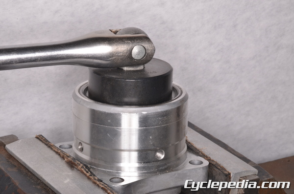
Apply a non-permanent thread locking agent (Blue Loctite) to the threads of the bearing holder. Do not contaminate the bearing with the locking agent. Thread in the bearing holder.
Tighten the bearing holder to specification with the special wrench.
Special Tool – Hexagon Wrench, Hex 41: 57001-1491
Bearing Holder
650cc: 118 N-m, 12 kgf-m, 87 ft-lb
700cc: 120 N-m, 12 kgf-m, 89 ft-lb
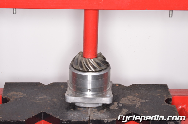
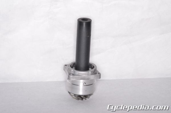
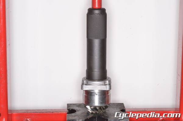
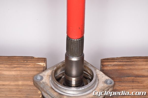
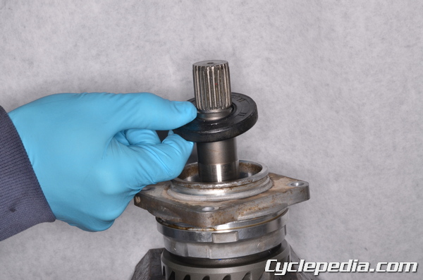
Press in the output bevel drive gear until it is fully seated.
Apply a non-permanent thread locking agent (Blue Loctite) to the threads of the bevel gear holder nut. Thread the nut onto the shaft.
Hold the gear from turning with the 17 mm Allen. Tighten the nut to specification with the special socket wrench tool.
Special Tool – Socket Wrench: 57001-1482
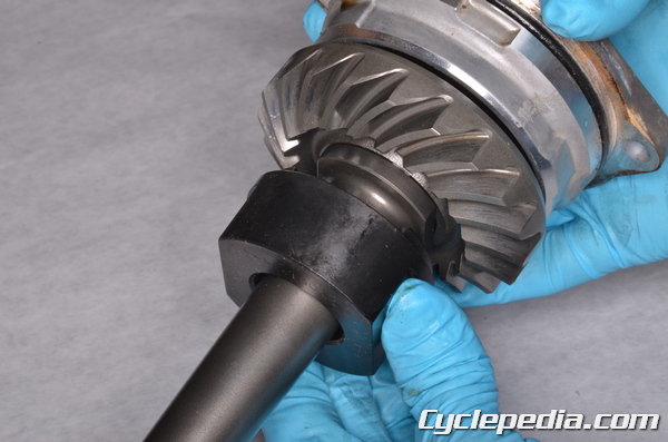
Press in the left bearing with a special tool that will fit around the shaft, but match up with the outside diameter of the bearing. Make sure the bearing is fully seated.
To install the output drive bevel gear see the Bevel Gear topic.
Output Driven Bevel Gear
Disassembly
The 2002 and 2003 models have a damper spring on the output driven shaft.
Use the special tools to compress the spring enough to remove the circlip.
Special Tools
Damper Spring Compressor Set: 57001-1475
Holder and Guide Arbor: 57001-1476
Circlip pliers: 57001-1476
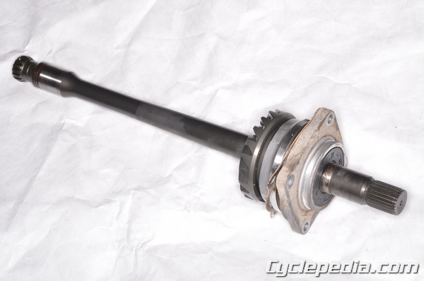
On the 2002 and 2003 models, remove the special tools and take off the spring holder, spring, cam damper, and output driven bevel gear.
Remove the O-ring from the output driven bevel gear housing. Fit the special tool onto the shaft.
Special Tool – Output Shaft Holder: 57001-1570
Secure the holder tool in a vise.
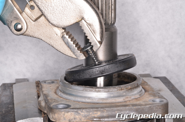
Remove the oil seal. A small wood screw can be threaded into the seal. Pull out on the screw and remove the oil seal.
The output shaft has a special holder nut that requires a special tool to loosen.
Loosen the output shaft holder nut with the special socket wrench.
Special Tool – Socket Wrench: 57001-1482
Remove the output shaft holder nut.
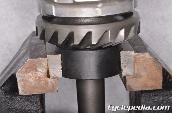
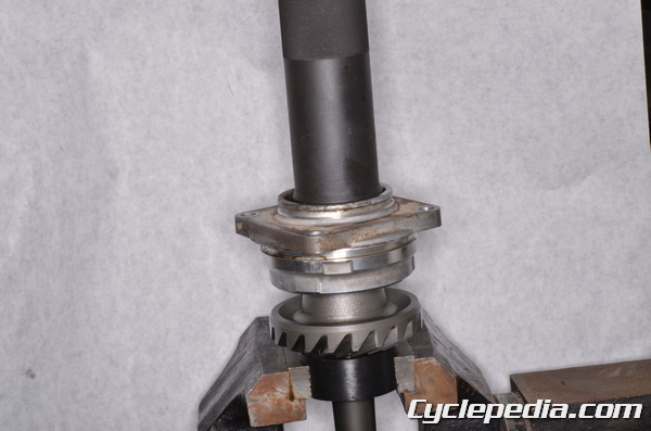
Press out the output shaft with a press.
Place the special holder tool into a vise and set the housing on the tool.
Special Tool – Holder and Guide Arbor: 57001-1476
Loosen the bearing holder nut with the special socket wrench. Heat the area around the holder nut if needed to free the thread locking agent.
Special Tool – Socket Wrench Hex 50: 57001-1478
Remove the bearing holder nut.
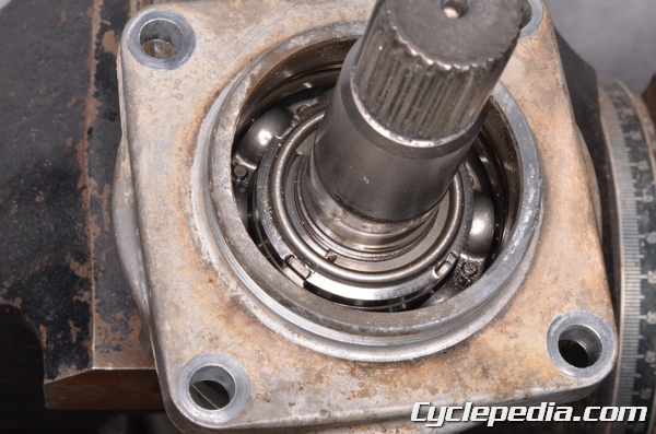
If the bearing needs to be replaced drive it out of the housing with a suitable bearing driver.
Special Tool – Oil Seal and Bearing Remover: 57001-1058
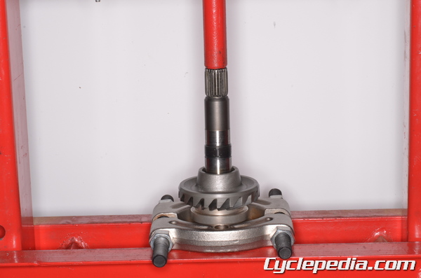
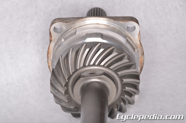
To remove the output driven bevel gear from its shaft use the special tools. A press, suitable spacer, and a universal bearing puller will also work.
Special Tools
Bearing Puller: 57001-135
Output Shaft Holder and Spacer, M 1.25: 57001-1129
Assembly
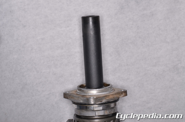
Drive in a new bearing with a suitable driver that is the same outside diameter as the bearing. Make sure the bearing is fully seated in the housing.
Special Tool – Bearing Driver Set: 57001-1058
Place the special holder tool into a vise and set the housing on the tool. Apply a non-permanent thread locking agent (Blue Loctite) to the threads of the bearing retainer nut. Do not contaminate the bearing with the locking agent.
Special Tool – Holder and Guide Arbor: 57001-1476
Install the bearing holder nut and tighten it to specification with the special socket wrench.
Special Tool – Socket Wrench Hex 50: 57001-1478
Bearing Holder
2002 – 2003, 700cc: 137 N-m, 14 kgf-m, 101 ft-lb
2005 – 2011: 250 N-m, 25.5 kgf-m, 184 ft-lb
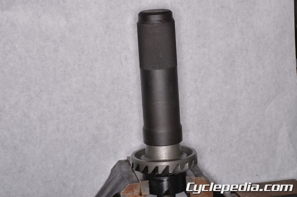
Fit the special tool onto the shaft. Secure the holder tool in a vise. Drive the output driven bevel gear onto the shaft until it is fully seated with the special driver.
Special Tools
Output Shaft Holder: 57001-1570
Steering Stem Bearing Driver: 57001-137
Drive the housing onto the shaft with the special tool.
Special Tool – Steering Stem Bearing Driver: 57001-137
Apply a non-permanent thread locking agent (Blue Loctite) to the threads of the output shaft holder nut. Thread the nut into place. Do not contaminate the bearing with the locking agent.
Tighten the output shaft holder nut to specification with the special socket wrench.
Special Tool – Socket Wrench: 57001-1482
Bevel Gear Holder Nut
2002 – 2003, 700cc: 157 N-m, 16 kgf-m, 116 ft-lb
2005 – 2011: 200 N-m, 20.4 kgf-m, 148 ft-lb
Lubricate the oil seal lips with grease. Press in the oil seal with a suitable driver that is the same outside diameter as the seal.
On the 2002 and 2003 models install the cam damper with its lobe facing the output driven bevel gear. Set the spring and spring holder over the cam damper.
Use the special tools to compress the spring enough to install the circlip and lock the spring into place on the shaft.
Special Tools
Damper Spring Compressor Set: 57001-1475
Holder and Guide Arbor: 57001-1476
Circlip pliers: 57001-1476
Install the bevel gears. See the Bevel Gear topic for more information.