
 Like this Manual?
SAFETY FIRST: Protective gloves and eyewear are recommended at this point.
Splitting
Drain the oil and remove the filter. See the Engine Oil topic for more information.
Remove the engine from the frame. See the Engine Removal topic for more information.
Remove the following engine components:
- Cylinder Head Covers
- Camshafts
- Cylinder Heads
- Cylinders
- CVT Cover
- Drive Belt
- Driven Pulley
- Recoil Starter
- Alternator
- Oil Pump
- Cam Chains
- Starter Motor
- Oil Pipes
Remove the bevel gear cover. See the Bevel Gear topic.
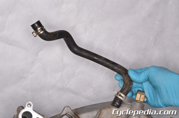
Remove the crankcase breather hose.
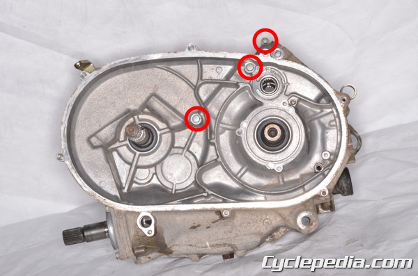
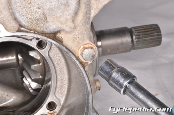
There are three right crankcase bolts.
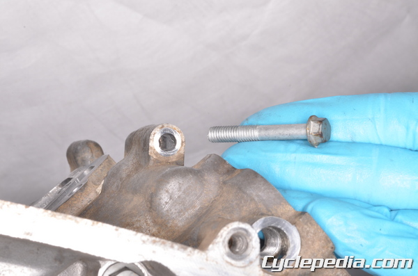
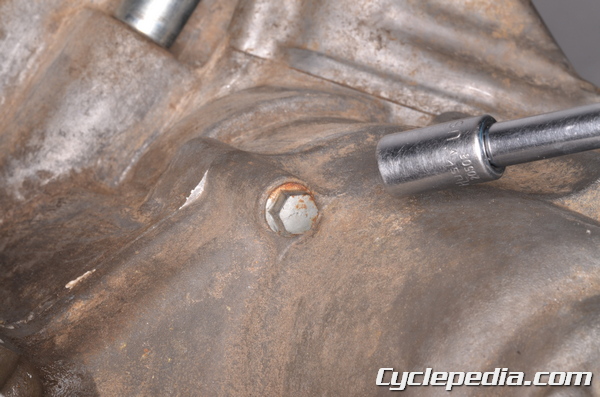
Remove the short right crankcase bolt with an 8 mm socket.
Remove the two longer right crankcase bolts with a 10 mm socket.
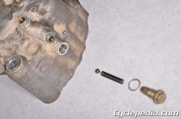
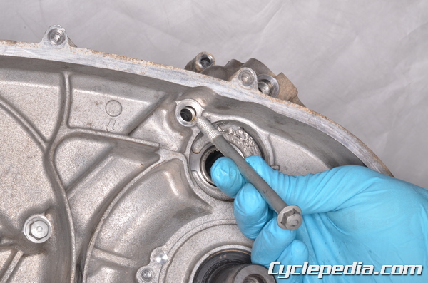
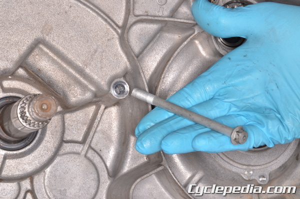
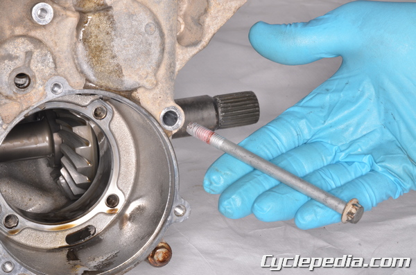
Remove the shift shaft positioning bolt with a 14 mm socket. Take out the washer spring and steel ball.
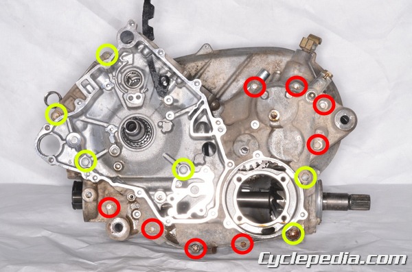
There are eight small left crankcase bolts and the six larger left crankcase bolts.
Use an 8 mm socket to remove the eight smaller bolts.
Use a 10 mm socket to remove the six larger bolts.
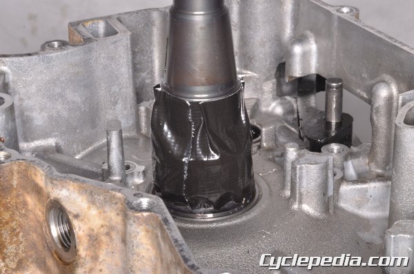
Cover the timing and oil pump drive sprocket teeth on the crankshaft with tape to protect them.
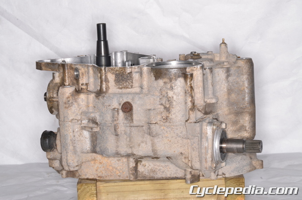
Set the crankcase on its right side.
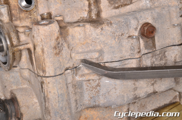
Utilize a pry bar on the reinforced pry points to separate the crankcase halves.
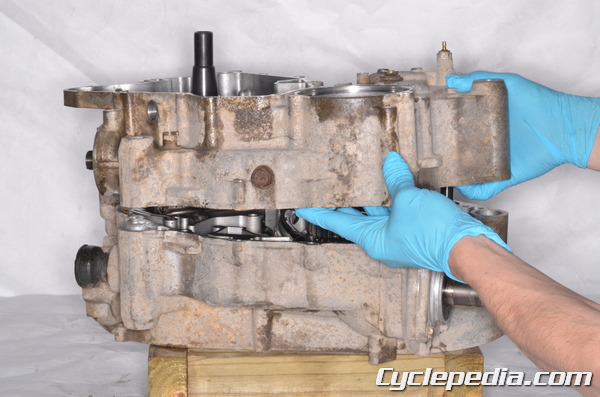
Lift the left crankcase half off of the right side.
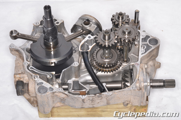
Clean the mating surfaces.
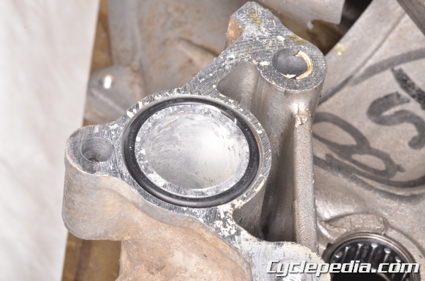
Remove the O-ring.

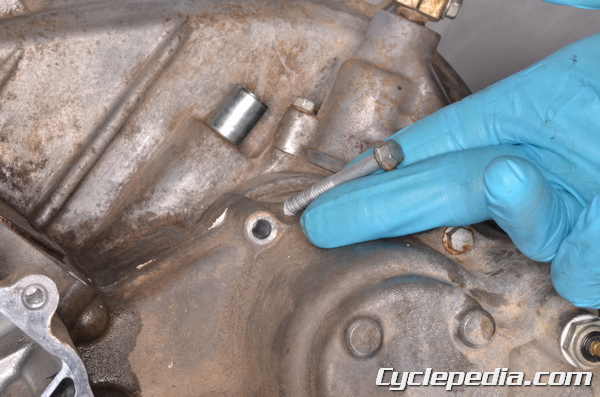
Remove the two dowel pins.
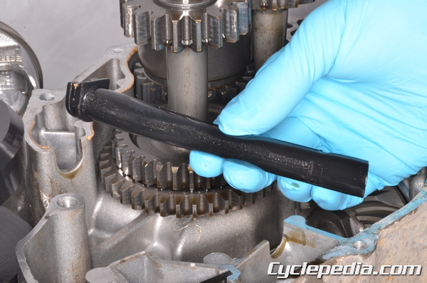
Remove the oil tube.
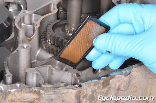
Remove the oil screen. Clean the oil screen with a high flash point solvent and compressed air.
To remove the crankshaft see the Crankshaft and Connecting Rods topic.
To remove the transmission see the Transmission Removal topic.
To inspect and replace the crankcase bearings see the Crankcase Bearings topic for more information.
To remove the bevel gear see the Bevel Gear topic.
Assembly
Make sure the crankcase mating surfaces are clean.
Install the oil screen into the right crankcase.
Install the oil tube into the right crankcase.
Install a new O-ring into the top of the right crankcase. Coat the O-ring in grease.
Install the two dowel pins into the right crankcase half.
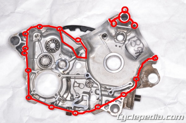
Apply liquid gasket to the left crankcase half as indicated by the line. Do not contaminate the bearings or oil passages with the liquid gasket.
Sealant – Liquid Gasket, TB1216: 92104-1063
Fit the left crankcase half onto the right.
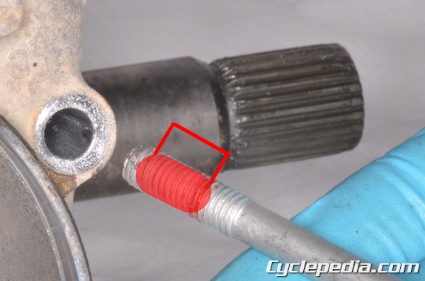
Apply a non-permanent thread locking agent (blue Loctite) to the threads of the #3 bolt. Coat the threads starting 2 – 3 mm back from the tip and over a 12 mm length of threads.
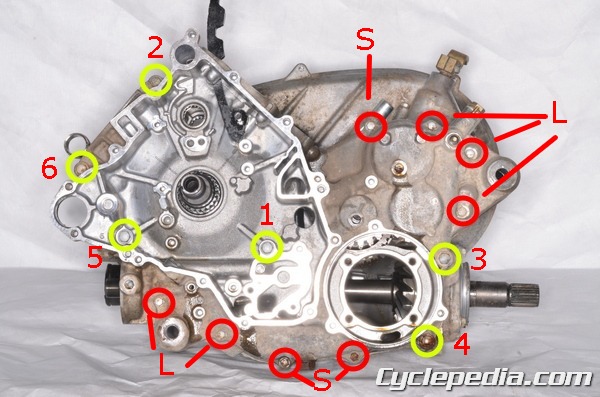
Install the left crankcase bolts. The front four M8 bolts (1,2,5,6) are 75 mm (2.95 in.) in length. The two rear M8 bolts (3 and 4) are 110 mm (4.33 in.) in length. Install the M6 bolts. The bolts marked “S” are 40 mm (1.57 in.) in length and the bolts marked “L” are 65 mm (2.56 in.) in length.
Install the right crankcase bolts. The right crankcase uses the longer M8 bolts and a short M6 bolt.
Tighten the M8 crankcase bolts evenly in the order listed starting with the left crankcase and then moving to the right. Torque the M8 crankcase bolts to specification with a 10 mm socket.
Crankcase Bolts (M8): 20 N-m, 2.0 kgf-m, 14 ft-lb
Tighten the M6 crankcase bolts evenly to specification with an 8 mm socket.
Crankcase Bolts (M6): 9.8 N-m, 1.0 kgf-m, 78 in-lb
Lubricate the steel ball and spring with grease. Install the steel ball, spring, washer, and shift shaft positioning bolt. Tighten the shift shaft positioning bolt to specification.
Shift Shaft Positioning Bolt: 25 N-m, 2.5 kgf-m, 18 ft-lb
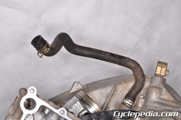
Install the crankcase breather hose so the white mark on the hose lines up with the mark on the crankcase.
Install the bevel gear cover. See the Bevel Gear topic.
Install the following engine components.
- Oil Pipes
- Starter Motor
- Cam Chains
- Driven Pulley
- Drive Belt
- Oil Pump
- Alternator
- Recoil Starter
- CVT Cover
- Cylinders
- Cylinder Heads
- Camshafts
- Cylinder Head Covers
Install the engine. See the Engine Installation topic.