
 Like this Manual?
SAFETY FIRST: Protective gloves and eyewear are recommended at this point.
Removal
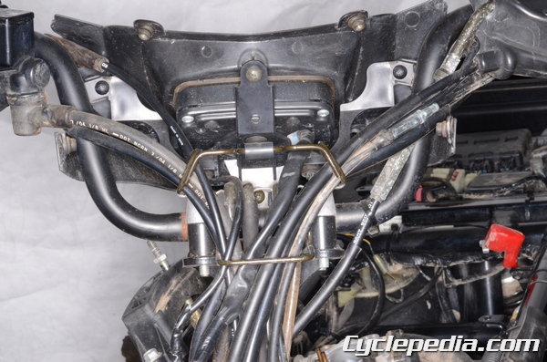
Remove the handlebar cover. See the Handlebar Cover topic for more information.
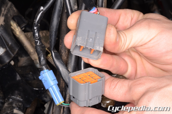
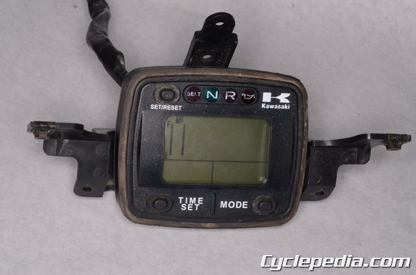
Unplug the display connector/s. The 2005 and newer 650 models have a single connector, where the older 650 and all 700 models have two connectors.
The rear handlebar cover and display bracket are mounted with four screws on the 2005 and newer 650 models and five screws on the older 650 and all 700 models.
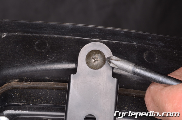
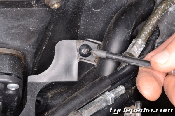
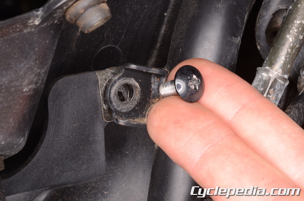
Remove the rear handlebar cover and display bracket screws with a #2 Phillips screwdriver.
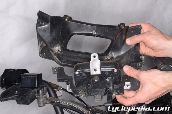
Lift off the rear handlebar cover.
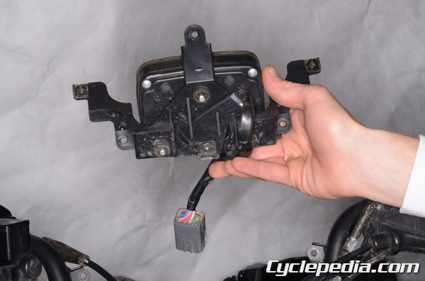
Remove the display and bracket.
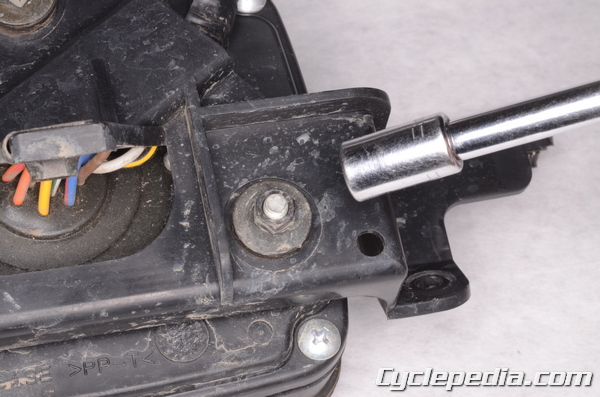
Loosen the display mounting nuts with an 8 mm socket.
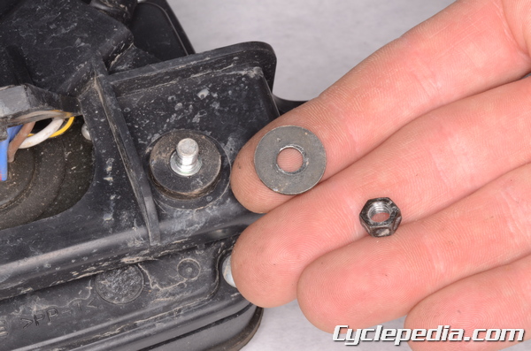
Remove the three nuts and washers.
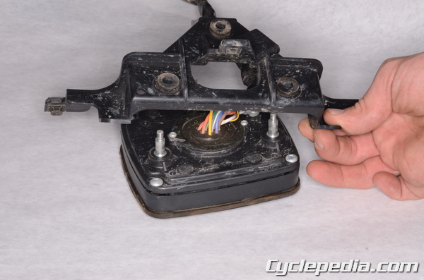
Lift the bracket off the back of the display.
Display Testing
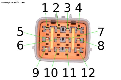
The 2005 and newer 650 models have a single display connector with 12 pins.
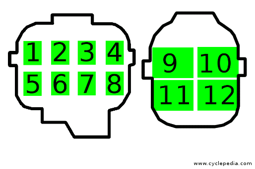
The 2002 – 2003 650 models and all of the 700 models have two connectors: an 8-pin and a 4-pin.
Refer to the pin numbers for testing the display.
LCD Segment Check
Single Connector
Jump a 12 Volt battery to the display. Touch the positive jump lead to the #10 and the negative jump lead to the #12. Touch an additional positive jump lead to the #9. When the jump is connected to the #9 all the LCD segments should show for one second. When the #9 jump is disconnected the LCD segments should disappear.
Replace the display if the LCD doesn’t function correctly.
Two Connectors
Jump a 12 Volt battery to the display. Touch the positive jump lead to the #9 and the negative jump lead to the #10. Touch an additional positive jump lead to the #11. When the jump is connected to the #11 all the LCD segments should show for one second. When the #11 jump is disconnected the LCD segments should disappear.
Replace the display if the LCD doesn’t function correctly.
MODE and TIME SET Buttons Check
Connect the 12 volt battery jump wires as with the LCD Segment Check.
Push and hold the MODE button. The display should cycle through all of its modes. EX. ODO, TRIP A, TRIP B, Hour, ODO. If the display fails to cycle through its modes it should be replaced.
Set the mode to TRIP A or B. When the SET/RESET button is pressed the trip should reset to 0.0. Replace the display if otherwise.
When the SET/RESET and TIME/SET buttons are pressed the time display should reset. Replace the display if otherwise.
Speedometer Check
Connect the 12 volt battery jump wires as with the LCD Segment Check.
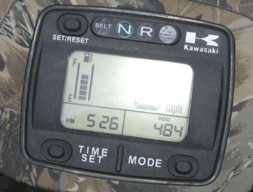
Use an oscillator to apply a square wave (0 – 5V Duty: 50 ± 25%) two the #1.
At about 789 Hz 40 mph should display.
At about 526 Hz 40 kmh should display.
Replace the display if otherwise.
Odometer and Trip Meter Check
Test the odometer as with the speedometer. Select the odometer or trip mode. Raise the oscillator frequency and check the odometer/trip function. If the odometer/trip fails to function replace the display.
Fuel Meter Check
Connect the 12 volt battery jump wires as with the LCD Segment Check. If the first segment of the fuel meter doesn’t flash the display should be replaced. On the 2002 models the fuel LED light should also flash.
In addition to the jumps already connected, jump an additional negative lead to the #5 pin. One segment in the fuel gauge should display every 15 seconds. Remove the jump to #5 when all fuel gage segments have appeared. Replace the display if the fuel gauge fails to show correctly.
2WD/4WD Check
Connect the 12 volt battery jump wires as with the LCD Segment Check.
The 2WD light should show.
In addition to the jumps already connected, jump an additional negative lead to the #4 pin.
The 4WD light should show. Replace the display if otherwise.
Coolant Temperature Warning Check
Connect the 12 volt battery jump wires as with the LCD Segment Check.
In addition to the jumps already connected, jump an additional negative lead to the #3 pin.
The coolant temperature warning indicator should show. Replace the display if otherwise.
Oil Pressure Warning Check
Single Connector
Connect the 12 volt battery jump wires as with the LCD Segment Check.
In addition to the jumps already connected, jump an additional negative lead to the #11 pin.
The oil pressure warning indicator should show. Replace the display if otherwise.
Two Connectors
Connect the 12 volt battery jump wires as with the LCD Segment Check.
In addition to the jumps already connected, jump an additional negative lead to the #12 pin.
The oil pressure warning indicator should show. Replace the display if otherwise.
Neutral Indicator Check
Connect the 12 volt battery jump wires as with the LCD Segment Check.
In addition to the jumps already connected, jump an additional negative lead to the #8 pin.
The neutral indicator should show. Replace the display if otherwise.
Reverse Indicator Check
Connect the 12 volt battery jump wires as with the LCD Segment Check.
In addition to the jumps already connected, jump an additional negative lead to the #7 pin.
The reverse indicator should show. Replace the display if otherwise.
Display Illumination Check
Connect the 12 volt battery jump wires as with the LCD Segment Check.
In addition to the jumps already connected, jump an additional positive lead to the #6 pin.
The display should light up. Replace the display if otherwise.
Belt Check Indicator Light Check
Connect the 12 volt battery jump wires as with the LCD Segment Check.
The Belt Check Indicator light should show.
2003 Models
Connect the 12 volt battery jump wires as with the LCD Segment Check.
In addition to the jumps already connected, jump an additional negative lead to the #2 pin.
The Belt Check Indicator light should show. Replace the display if otherwise.
Installation
Fit the bracket onto the display.
Install the three washers and nuts.
Tighten the nuts securely with an 8 mm socket.
Fit the display and rear handlebar cover into place.
The rear handlebar cover and display bracket are mounted with four screws on the 2005 and newer 650 models and five screws on the older 650 and all 700 models.
Install the rear handlebar cover and display bracket screws with a #2 Phillips screwdriver.
Plug the display connector/s. The 2005 and newer 650 models have a single connector, where the older 650 and all 700 models have two connectors.
Install the handlebar cover. See the Handlebar Cover topic for more information.