
 Like this Manual?
SAFETY FIRST: Protective gloves and eyewear are recommended at this point.
Removal
Alternator Cover
Drain the coolant. See the Coolant topic for more information.
Drain the engine oil. See the Engine Oil topic for more information.
Remove the recoil starter or cover. See the Recoil Starter topic fore more information.
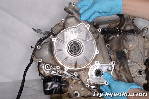
Remove the water pump. See the Water Pump topic for more information.
Remove the CVT cover. See the CVT Cover topic for more information.
On the 2002 model a hook wrench may be used to hold the recoil starter pulley instead of using the drive pulley holder.
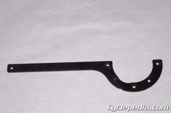
In order to remove the alternator on the 2003 and newer models a special drive pulley holder tool is needed.
Special Tool – Drive Pulley Holder: 57001-1520

Locate the arrow on the face of the drive pulley. Using a 10 mm socket to remove the three drive pulley cover bolts that will secure the tool in place. Position the tool on the pulley and reinstall the three bolts. Tighten the bolts to specification.
Drive Pulley Cover Bolts: 13 N-m, 1.3 kgf-m, 113 in-lb
Hold the crankshaft from turning with either the hook wrench or the drive pulley holder. Loosen the alternator rotor bolt with a 19 mm socket. Remove the alternator rotor bolt.
Remove the recoil starter pulley on models equipped with a recoil starter.
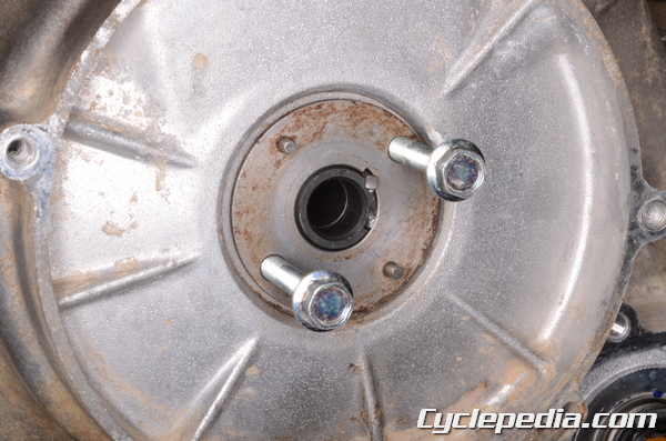
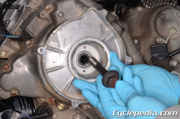
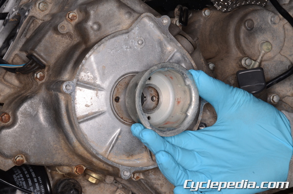
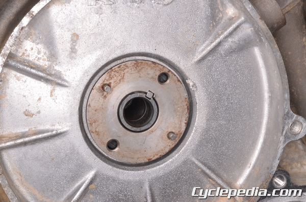
Thread to M6 bolts into the collar. Pull straight out on the bolts and remove the collar.
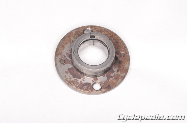
Make sure the O-ring on the collar is good condition.
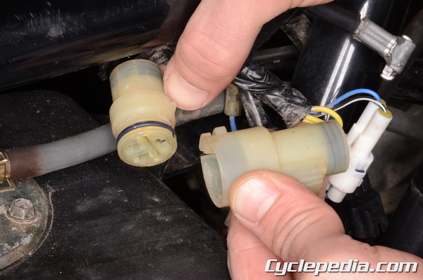
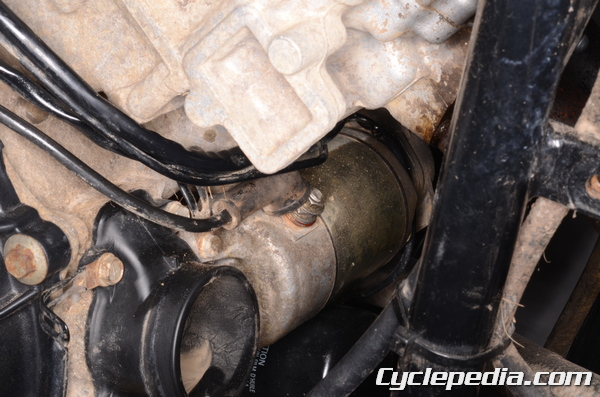
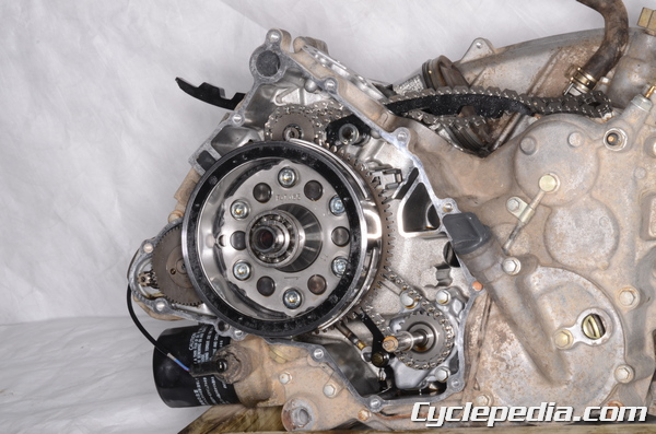
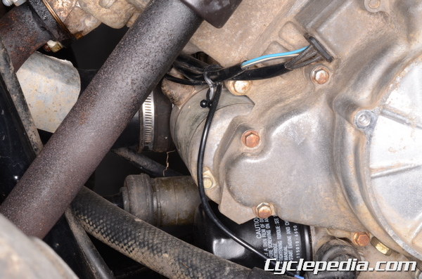
The alternator wires wrap around the front of the engine and up to the right side of the frame. Unplug the alternator 3-pin connector.
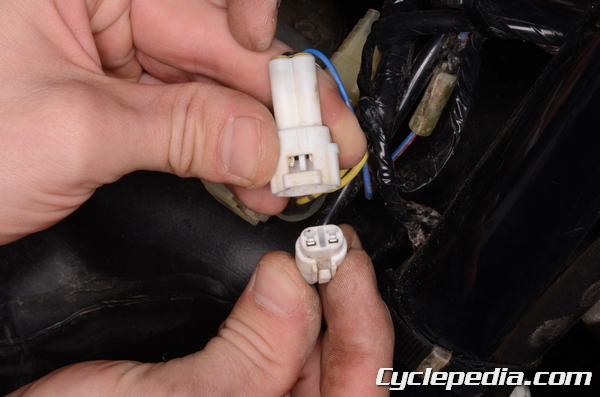
Unplug the 2-pin pickup coil/crank position sensor connector.
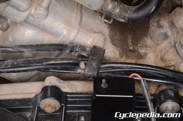
Free the alternator and pickup coil/crank position sensor wires so they can come out with the cover.
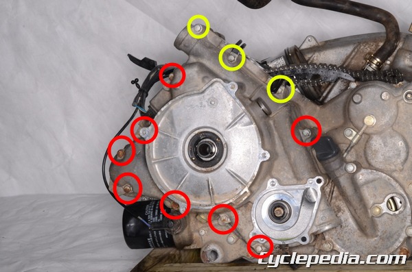
Place an oil pan under the left side of the engine. There are 11 alternator cover bolts.
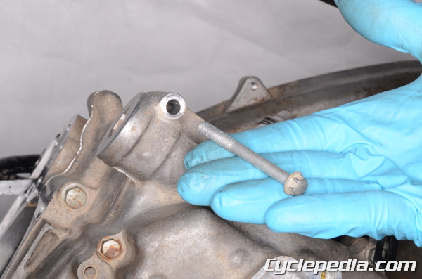
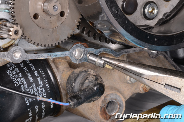
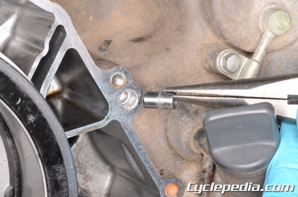
Remove the alternator cover bolts with an 8 mm socket.
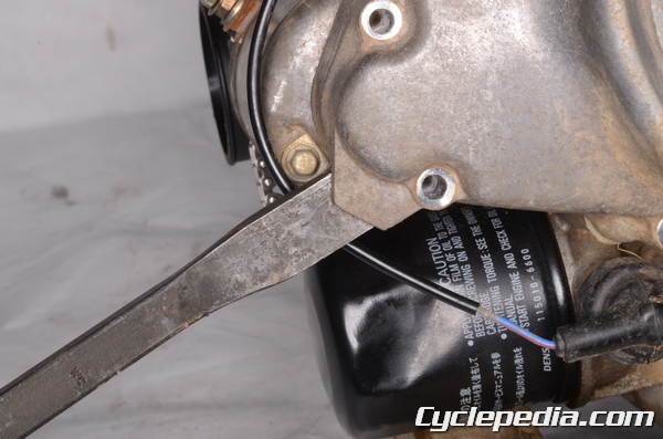
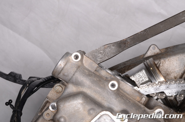
Utilize the pry points to free the cover.
Remove the alternator cover keeping it as even as possible to avoid binding from the magnetic force of the rotor.
Remove the alternator cover gasket.
Remove the recoil starter key from the left end of the crankshaft.
Remove the two dowel pins.
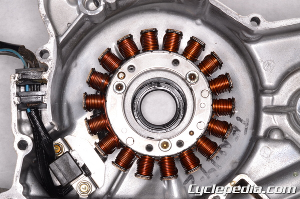
Stator and Pickup Coil/Crank Position Sensor
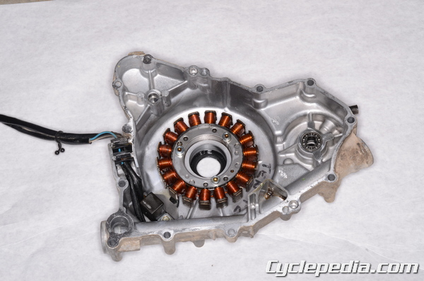
The stator and pickup coil/crank position sensor are located on the inside of the alternator cover. Free the rubber wire grommets from the cover.
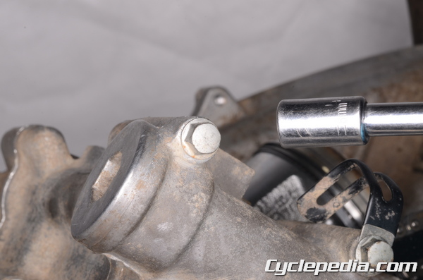
To remove the stator coil remove the three bolts with a 5 mm Allen socket.
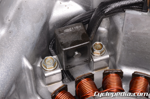
To remove the pickup coil/crank position sensor remove the two bolts with an 8 mm socket.
Alternator Rotor (Flywheel)
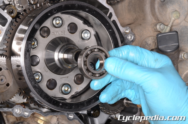
Remove the bearing from the left end of the crankshaft if it was seized to the crankshaft like ours. This bearing should come off with the cover.
It may be necessary to use a bearing puller to remove the bearing from the crankshaft.
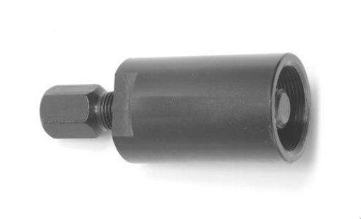
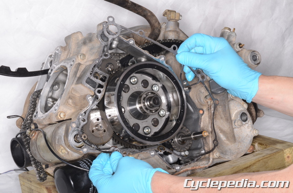
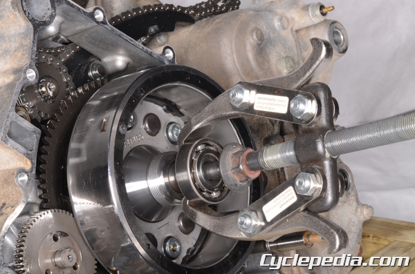
A flywheel puller will be needed to remove the flywheel from the crankshaft.
Special Tool – Flywheel Puller Assembly M38x1.5/M35x1.5: 57001-1405
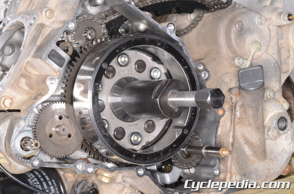
Lubricate the flywheel puller threads with grease. Thread the puller onto the flywheel. Hold the puller and turn in the pusher bolt to separate the flywheel from the crankshaft.
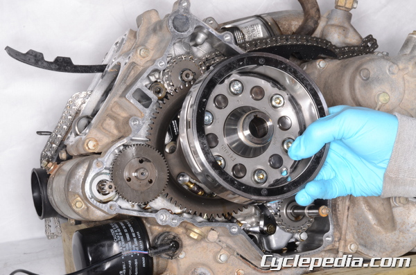
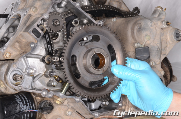
Remove the flywheel from the left side of the crankshaft.
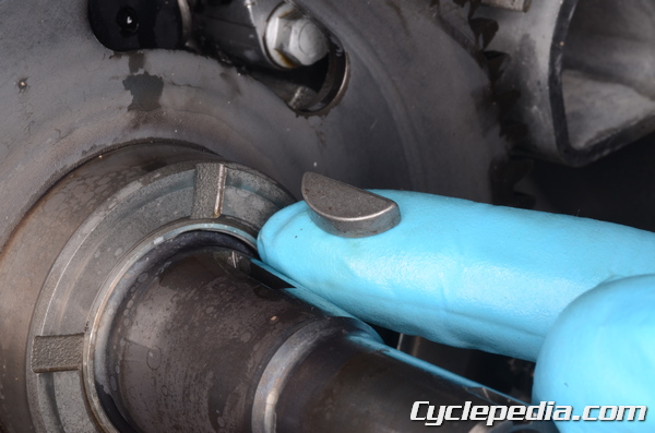
Remove the flywheel key from the crankshaft.
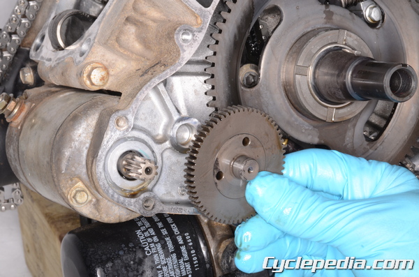
Remove the torque limiter gear.
Remove the starter clutch gear.
Alternator Cover Seal
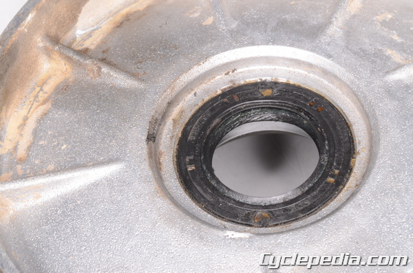
Inspect the alternator cover oil seal. Replace the seal as needed. If the seal is to be replaced drive it in from the outside with a suitable driver that is the same diameter as the seal. Coat the lips of the seal in grease.
Installation
Stator and Pickup Coil/Crank Position Sensor
Install the stator coil and crank position senor/pickup coil into the alternator cover. Fit the wire grommets into the cover. Tighten the three stator coil bolts to specification using a 5 mm Allen socket.
Alternator Stator Bolts: 13 N-m, 1.3 kgf-m, 113 in-lb
Tighten the crank position senor/pickup coil bolts to specification with an 8 mm socket.
Pickup Coil/Crankshaft Sensor Mounting Bolts: 5.9 N-m, 0.6 kgf-m, 52 in-lb
Flywheel
Place the starter clutch gear on the crankshaft.
Install the torque limiter into the crankcase.

Make sure the tapered portion of the crankshaft is clean and oil free. Install the flywheel key into its groove.
Fit the flywheel onto the crankshaft.
Alternator Cover
Place the bearing on the crankshaft. Install the recoil starter key into the groove on the end of the crankshaft.
Make sure the alternator cover mating surface is clean.
Install the two dowel pins.
Install a new alternator cover gasket.
Apply grease to the lips of the alternator cover oil seal. Fit the alternator cover into place.
Install the 11 alternator cover bolts.
Tighten the alternator cover bolts to specification with an 8 mm socket.
Alternator Cover Bolts: 8.8 N-m, 0.9 kgf-m, 78 in-lb
Apply grease to the O-ring on the collar.
Install the collar so that its groove fits on the recoil starter key on the crankshaft.
Install the recoil starter pulley so that the pins on the collar fit into the holes on the pulley. Install the alternator rotor bolt.
On the 2002 model a hook wrench may be used to hold the recoil starter pulley instead of using the drive pulley holder.
Locate the arrow on the face of the drive pulley. Using a 10 mm socket remove the three cover bolts that will be used to hold the tool in place.
Special Tool – Drive Pulley Holder: 57001-1520
Position the tool on the pulley and reinstall the three bolts. Tighten the bolts to specification.
Drive Pulley Cover Bolts: 13 N-m, 1.3 kgf-m, 113 in-lb

Hold the crankshaft from turning with either the hook wrench or the drive pulley holder. Torque the alternator rotor bolt with a 19 mm socket.
Alternator Rotor Bolt: 127 N-m, 13 kgf-m, 94 ft-lb
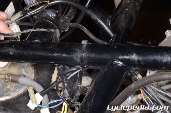
Route alternator wires around the front of the engine and up to the right side of the frame as with the oil pressure switch.
Plug in the alternator 3-pin connector.
Plug in the 2-pin pickup coil/crank position sensor connector.
Secure the alternator and pickup coil/crank position sensor wires with the clamps on the front and right side of the engine and install a wire band on the right side of the frame.
Install the CVT cover. See the CVT Cover topic for more information.
Install the water pump impeller. See the Water Pump topic for more information.
Install the recoil starter or cover. See the Recoil Starter topic fore more information.
Fill engine oil. See the Engine Oil topic for more information.
Fill and bleed the coolant. See the Coolant topic for more information.