
 Like this Manual?
SAFETY FIRST: Protective gloves and eyewear are recommended at this point.
Removal
Drain the oil from the front differential. See the Final Gear Case Oil topic for more information.
Remove the front wheels. See the Wheels and Hubs topic for more information.
Remove the front inner cover/s and the lower shroud. See the Inner Covers topic for more information.
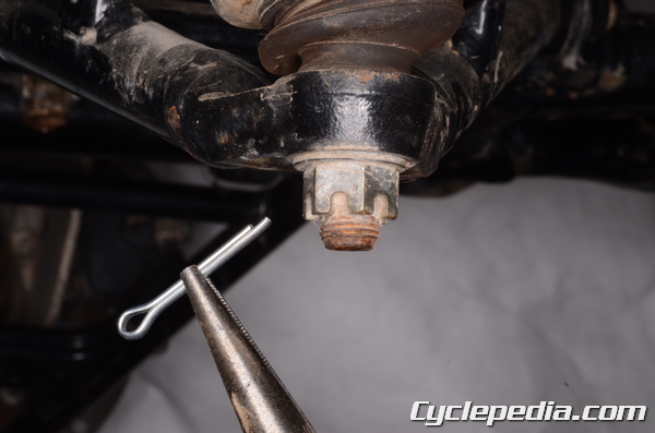
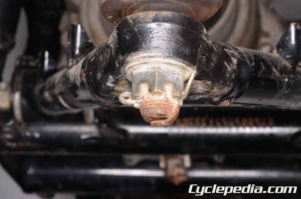
Remove the cotter pin from the knuckle ball joint nut.
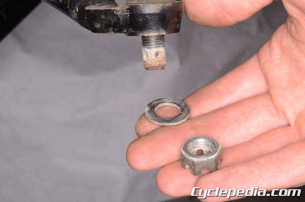
Loosen knuckle ball joint nut with a 17 mm socket. Remove the nut and the washer. Free the knuckle from the suspension arm.
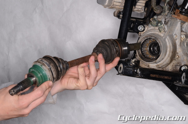
Pull the axle straight out from the front differential.
Inspection
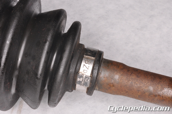
Use a shop rag to clean the old grease from the front axles. Check the axle for bends or damage. Check the boots and boot bands for any damage or excessive wear. Replace parts as needed.
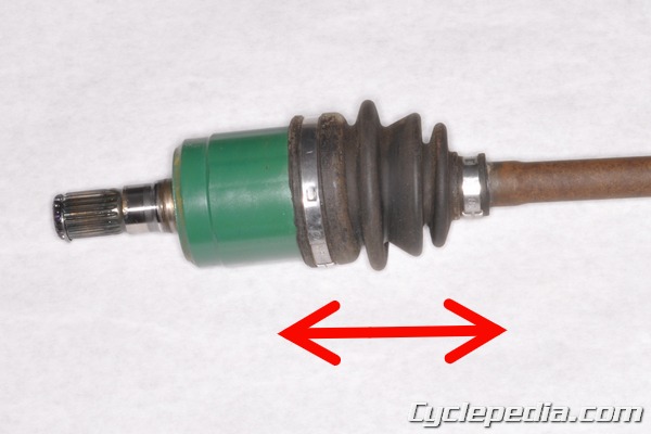
Push and pull on the axle shaft and wheel spindle to check the play in the axle.
Disassembly
Note: Do not disassemble the wheel side joint, just replace it with a new one if there is any damage.
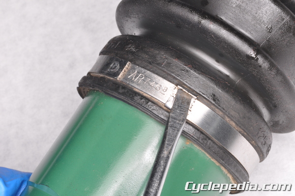
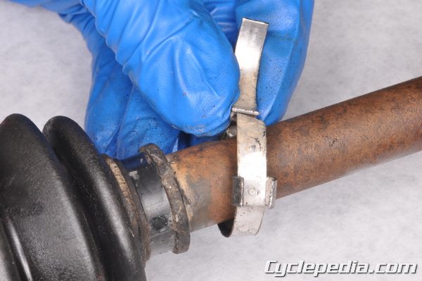
Use a flatblade screwdriver to carefully bend the tabs of the boot band lock open.
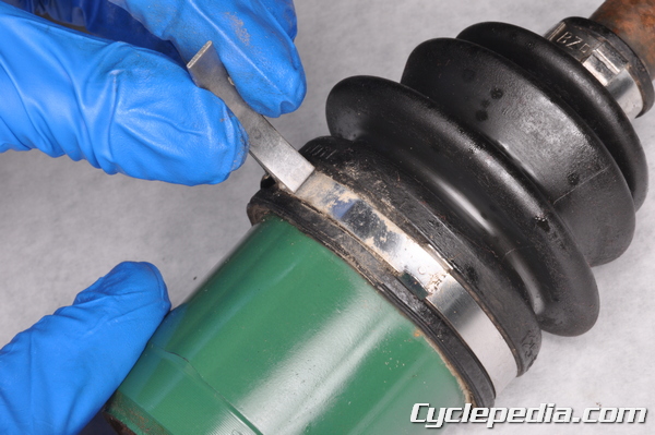
Free the boot band end from the lock.
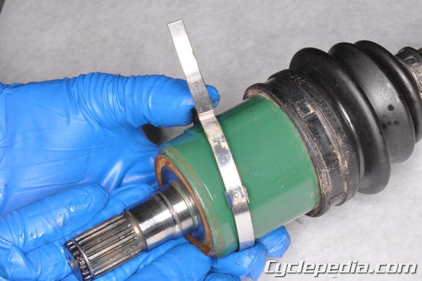
Remove and discard the band.
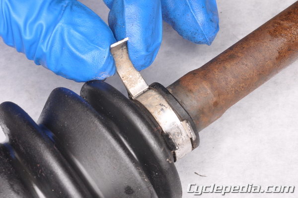
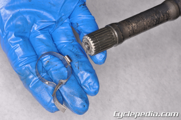
Carefully free the small diameter boot band in the same manner.
Remove the small diameter boot band.
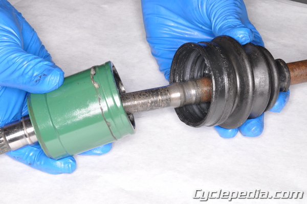
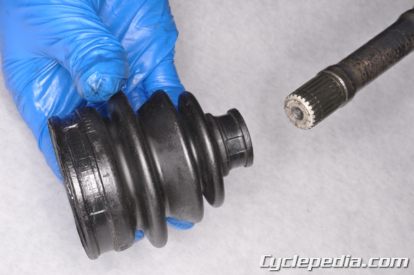
Pull the boot off the outer race.
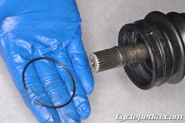
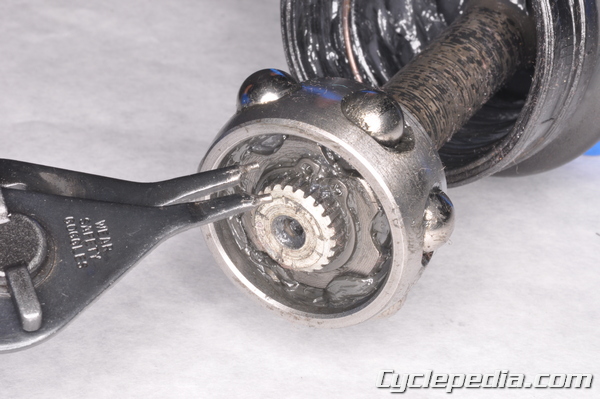
Free the stopper ring from the outer race with a flat head screwdriver.
Remove the stopper ring.
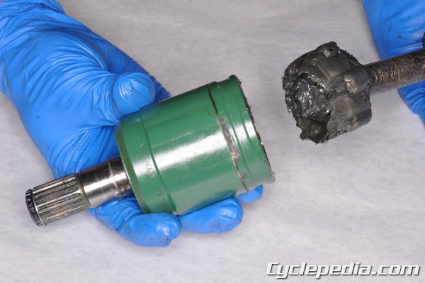
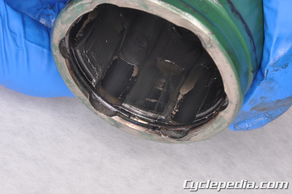
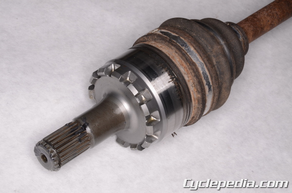
Remove the outer race.
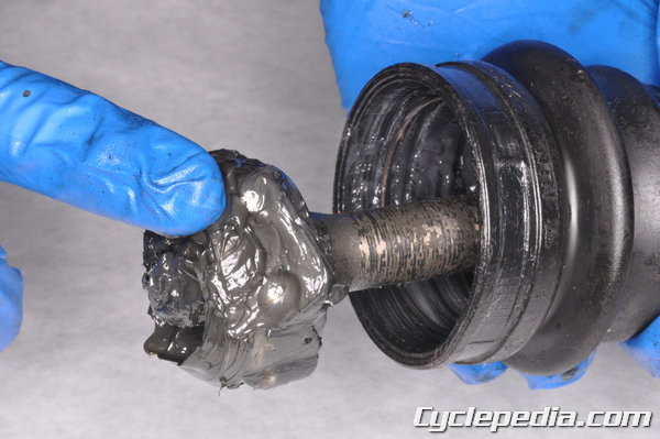
Wipe off any grease from the cage.
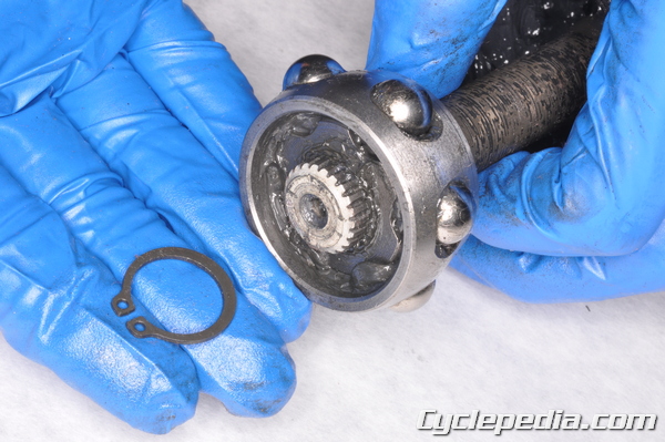
Remove the cage and steel balls. Remove the snap ring with a pair of snap ring pliers. Replace the snap ring as needed.
Remove the inner ball race with a universal bearing puller.
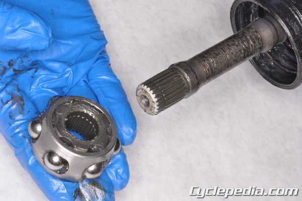
Inspect the cage for binding or damage. Remove the cage and replace as needed. Note the smaller diameter side faces inward.
Remove the stopper ring and replace as needed.
Remove the boot. Clean the boot with a clean shop rag. Inspect the boots and replace if they are damaged.
Remove and discard the boot bands if you haven’t already.
Inspection
Inspect the outer race for excessive wear or damage.
Clean all the parts and dry them with compressed air, except for the boots. Clean the boots with a clean shop rag.
Installation
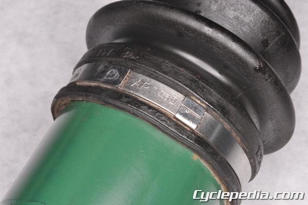
Install a new boot band onto the shaft groove end. The end of the boot band should face away from the rotation of the drive shaft.
Install the boot into the shaft groove end. Install the stopper ring and cage onto the shaft. The wide side of the cage should face towards the differential side of the axle.
Tighten the clamp tight enough to keep the boot in place, but loose enough to allow the free turning of the axle shaft. Take care not to damage the boot.
Drive the inner ball race onto the shaft so that its flat side faces towards the wheel.
Special Tool – Rotor Puller: 57001-1216
Fit the cage and balls onto the inner race. Install the snap ring with a pair of snap ring pliers.
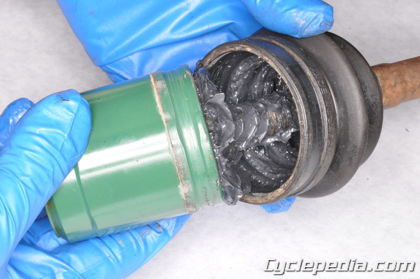
Coat the entire cage and the inside of the outer race with grease. Install the cage into the outer race. Use a bout a half tube of the special grease (30g).
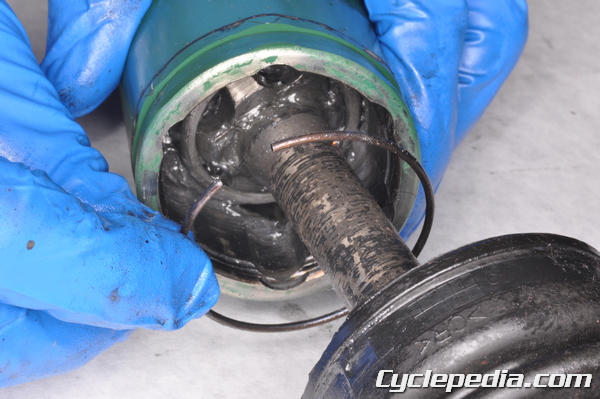
Install the stopper ring into the outer race groove. Be sure that the open ends of the stopper ring do not line up with the ball bearing slots.
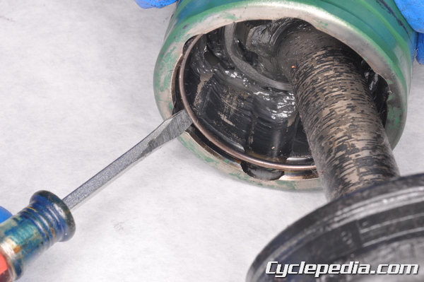
Install the boot onto the outer race. Carefully insert a flat blade screw driver between the boot and outer race to equalize the air pressure.
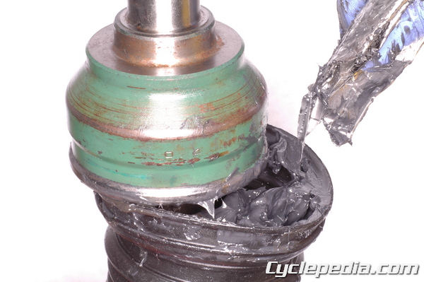
Pull the boot up to the CV joint. Squeeze some grease into the bottom of the boot. Try not to get the grease on the boot where it will contact the CV joint housing. Use the full tube of special grease (~ 60g) for the wheel side boot, and about a half tube for the differential side boot (~35g).
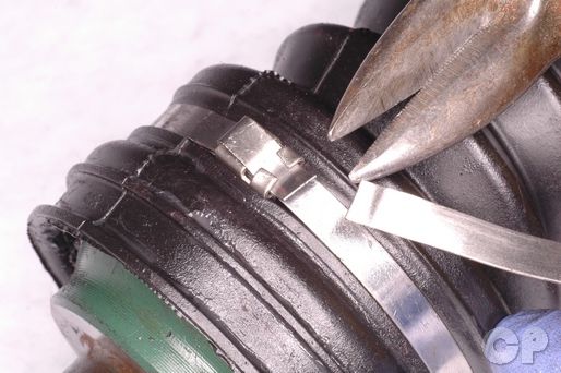
Install a new boot band over the boot and outer race. Take care not to damage the boot. Secure the clamp by closing the buckle tabs against the clamp tail with a flat faced punch and a hammer.
Note: The end of the boot band should face away from the rotation of the drive shaft.
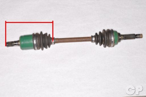
Check that the distance between the shaft end and small diameter boot band are within specification. Compress the joints for the measurements.
Right Axle
Wheel Side: 178 mm (7.01 in.)
Differential Side: 161.1 mm (6.34 in.)
Left Axle
Wheel Side: 178 mm (7.01 in.)
Differential Side: 169.1 mm (6.66 in.)
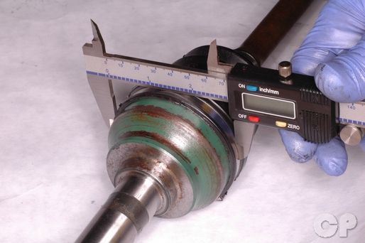
Measure the boot clamps with Vernier calipers as indicated.
Clamp Wheel Side Differential Side
2002 – 2003
Small Clamp: 26.1 ± 0.3 mm (1.028 ± 0.012 in.)
Large Clamp: 69.0 ± 0.3 mm (2.717 ± 0.012 in.)
2004 and Newer
Wheel Side: 73.1 mm (2.88 in.)
Differential Side: 69 mm (2.72 in.)
Cutoff any extra band on the clamps on the 2002 – 2003 models.
Installation
Lubricate the axle splines with molybdenum disulfide grease.
Lubricate the front axle seals on the differential with grease. Fit the front axle into the differential.
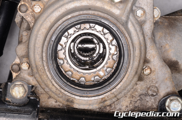
Make sure the teeth on the left axle fit into the clutch in the differential.
Fit the knuckle ball joint into the suspension arm. Fit the shock absorber into the knuckle.
Install the washer and nut onto the knuckle ball joint. Tighten knuckle ball joint nut to specification with a 17 mm socket.
Steering knuckle joint nut (2006 – 2011): 29 N-m, 3.0 kgf-m, 21 ft-lb
Install a new cotter pin and bend it to secure the nut.
Install the front inner cover/s and the lower shroud. See the Inner Covers topic for more information.
Install the steering knuckle. See the Steering Knuckles topic for more information.
Install the front wheels. See the Wheels and Hubs topic for more information.
Fill the oil from the front differential. See the Final Gear Case Oil topic for more information.