
 Like this Manual?
SAFETY FIRST: Protective gloves and eyewear are recommended at this point.
Inspection
The engine has to be cold to check the valve clearance.
Remove the air cleaner cover. See the Air Filter Servicing topic for more information.
Remove the front fender. See the Front Fender topic for more information.
Remove the inner cover rear on 650 models. See the Inner Covers topic for more information.
Remove the front inner covers on 700 models. See the Inner Covers topic for more information.
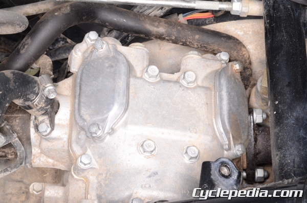
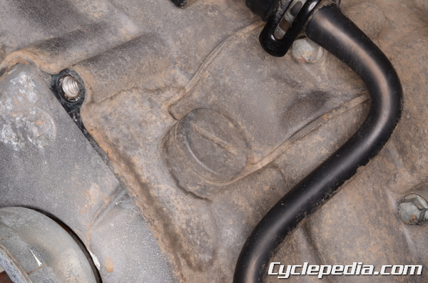
There are two valve adjusting covers per cylinder head.
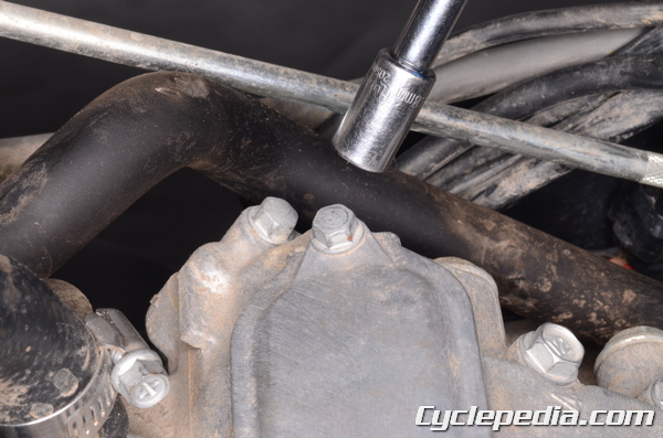
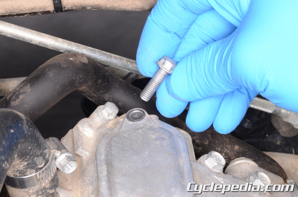
Remove the valve adjusting cover bolts with an 8 mm socket.
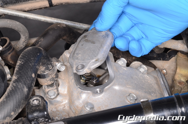
Lift off the valve adjusting covers.
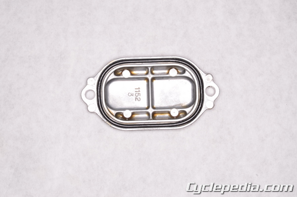
Inspect the valve adjusting cover O-rings and replace them as needed.
Remove the recoil starter. See the Recoil Starter topic for more information.
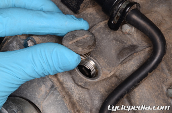
Remove the timing inspection plug with a filler cap driver. Inspect the inspection plug O-ring and replace as needed.
Special Tool-
Filler Cap Driver: 57001-1454
Front Cylinder
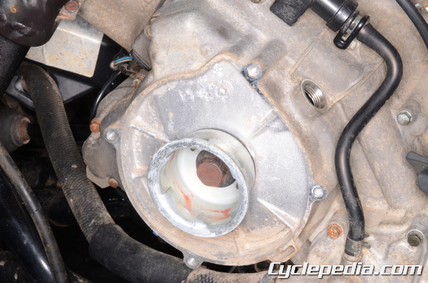

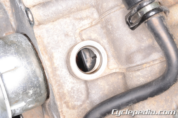
Turn the crankshaft counterclockwise with a 19 mm socket until you observe the intake valves of the front cylinder head open and then close. You will see the valves move downward as they open and move upwards as they close.
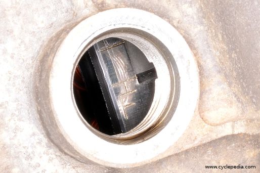
Stop the turning the crankshaft when he “T-F” mark on the generator rotor aligns with the indicator on the case cover. Check the valve clearance for all four valves of the front cylinder.
Measure the valve clearance with a thickness feeler gauge. Insert the feeler gauge between the adjusting screw and the valve stem. The clearance is correct when there is a light drag on the feeler gauge. If the clearance is out of spec move on to the adjustment section.
| Front Cylinder Valve Clearance (Cold) |
Intake | 0.10 – 0.15 mm (0.0039 – 0.0059 in) |
| Exhaust | 0.20 – 0.25 mm (0.0079 – 0.0098 in) |
Rear Cylinder
Turn the crankshaft counterclockwise with a 19 mm socket until you observe the intake valves of the rear cylinder head open and then close. You will see the valves move downward as they open and move upwards as they close.
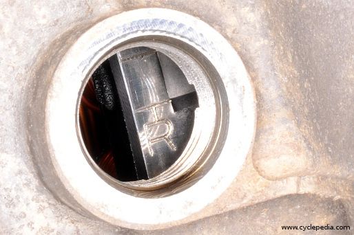
Stop the turning the crankshaft when he “T-R” mark on the generator rotor aligns with the indicator on the case cover. Check the valve clearance for all four valves of the rear cylinder. The “T-R” mark is 270° counterclockwise from the “T-F” mark.
Measure the valve clearance with a thickness feeler gauge. Insert the feeler gauge between the adjusting screw and the valve stem. The clearance is correct when there is a light drag on the feeler gauge. If the clearance is out of spec move on to the adjustment section.
| Rear Cylinder Valve Clearance (Cold) |
Intake | 0.10 – 0.15 mm (0.0039 – 0.0059 in) |
| Exhaust | 0.20 – 0.25 mm (0.0079 – 0.0098 in) |
Adjustment
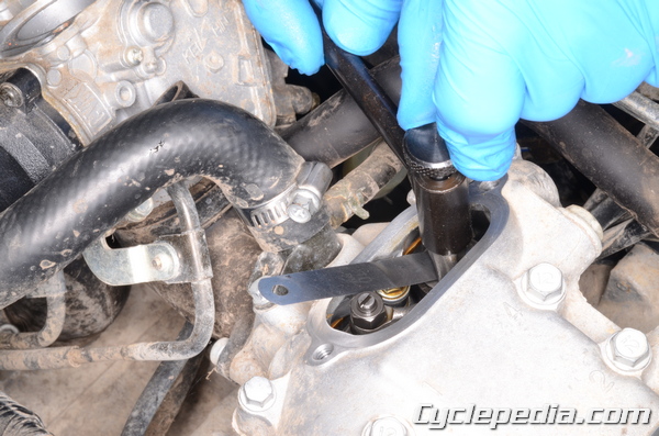
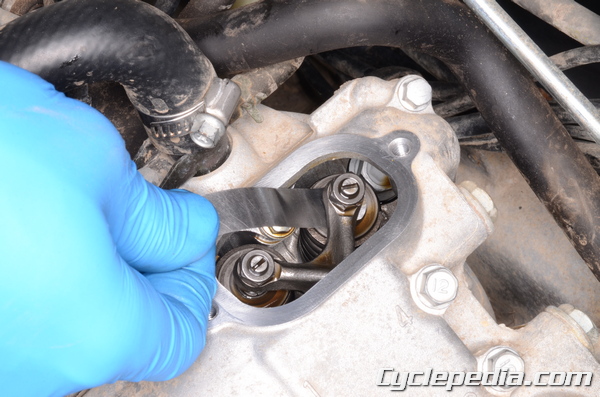
Use a valve adjuster tool to adjust the valves. Place the wrench part of the adjuster tool over the locknut, and loosen the locknut. You can also use a 10 mm wrench to loosen the locknut.
If the valve clearance is to tight back out the valve adjusting screw with the valve adjustment tool. If the clearance is too loose turn in the valve adjusting screw until there is a light drag on the feeler gauge. Hold the adjusting screw locknut in place with the wrench part of the tool (10 mm) to make sure it doesn’t interfere with the adjustment. Hold the adjuster in place when you tighten the locknut. Always recheck the clearance after tightening the locknut.
| ITEM | N-m | kgf-m | Ib-ft | |
| Valve Clearance Adjuster Locknut | 12 | 1.2 | 104 in-lb | |
Assembly
Install a new O-ring on the inspection plug. Install the timing inspection plug and tighten securely with a filler cap driver or large flat blade screwdriver. Do not over tighten these plugs as they can be easily damaged.
Special Tool-
Filler Cap Driver: 57001-1454
Apply grease to the new O-rings and install them onto the valve adjusting covers.
Install the valve adjusting covers.
Tighten the valve adjusting cover bolts to specification with an 8 mm socket.
| Fastener | Torque | ||
| N-m | kgf-m | ft-lb | |
| Valve adjusting cover bolt | 8.8 | 0.9 | 78 in-lb |
Install the recoil starter. See the Recoil Starter topic for more information.
Install the inner cover rear. See the Inner Covers topic for more information.
Install the front fender. See the Front Fender topic for more information.
Install the air cleaner cover. See the Air Filter Servicing topic for more information.