
 Like this Manual?
SAFETY FIRST: Protective gloves and eyewear are recommended at this point.
Clean the final drive gear case components with a high flash point solvent and compressed air.
NOTE: Always wear safety glasses when using compressed air and never point it directly at yourself or anyone else.
Lubricate the side gears (16T) with molybdenum disulfide grease. Lubricate the bearings, spider gears (10T) and the spider gear shaft with fresh oil.
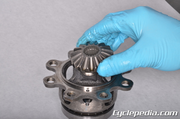
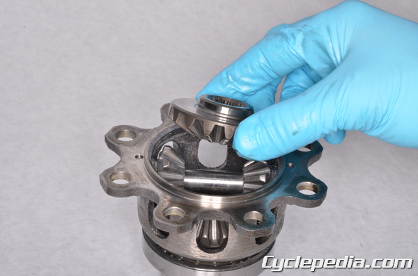
Fit the left side gear (16T) into the spider gear case.
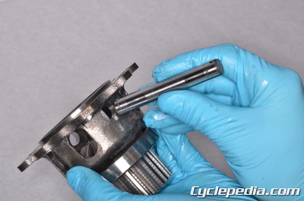
Insert the spider gear shaft. The holes in the ends of the spider gear shaft must line up with the holes in the spider gear case.
Install the spider gears (10T) onto the shaft as the shaft is pushed through the spider gear case.
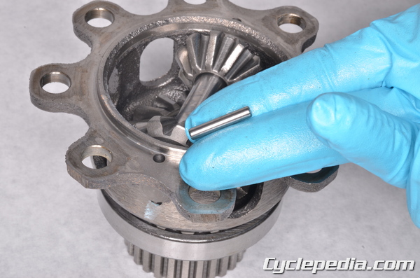
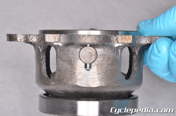
Install the to pins to secure the spider gear shaft.
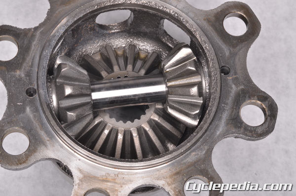
Install the right side gear (16T).
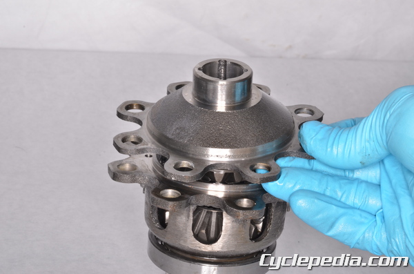
Fit the spider gear case cover into place.
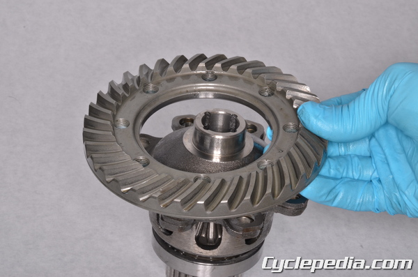
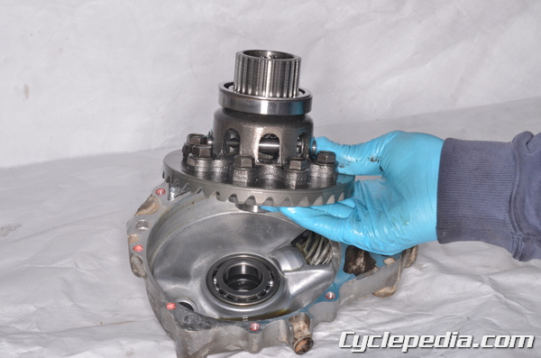
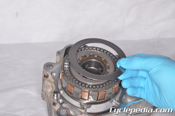
Set the ring gear onto the spider case cover.
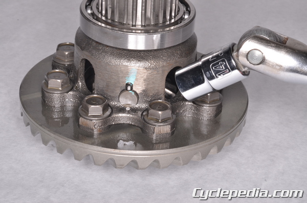
Apply a non-permanent thread locking agent (Blue Loctite) to the eight ring gear bolts. Torque the ring gear bolts to specification with a 14 mm socket. When installing the ring gear it is important that the ring gear assembly remain at a temperature greater than 20° C or 68° F for at least six hours after installing the bolts.
Ring Gear Bolts: 57 N-m, 5.8 kgf-m, 42 ft-lb

Install the pinion gear shim/s into the right differential case.
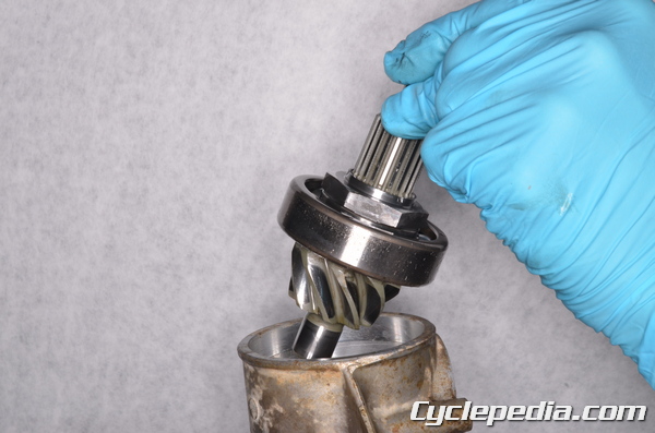
Install the pinion gear into the right differential case. For information on selecting the correct shim/s see the Differential Inspection topic.
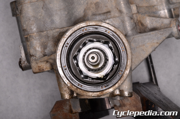
Secure the right differential case in a soft jawed vise. Apply a non-permanent thread locking agent (Blue Loctite) to the threads of the pinion gear bearing holder nut. Do not contaminate the bearing with the locking agent. Thread the bearing holder nut into the differential case so that its recessed side face up.
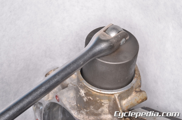
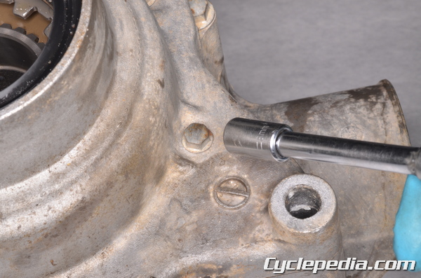
Tighten the bearing holder nut to specification with the special socket wrench.
Special Tool – Socket Wrench Hex 41: 57001-1484
Pinion Gear Bearing Holder: 137 N-m, 14 kgf-m, 101 ft-lb
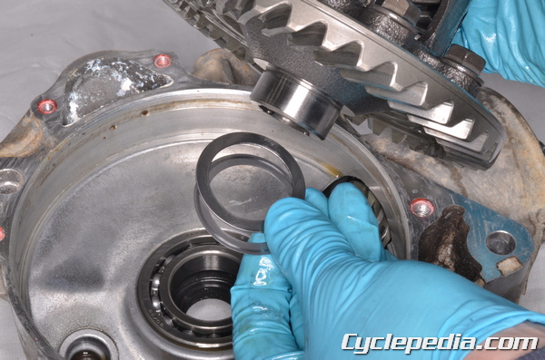
Install the right ring gear shim/s and the ring gear assembly into the right differential case.
For information on selecting the correct shim/s see the Differential Inspection topic.
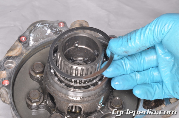
Install the left ring gear shim/s.
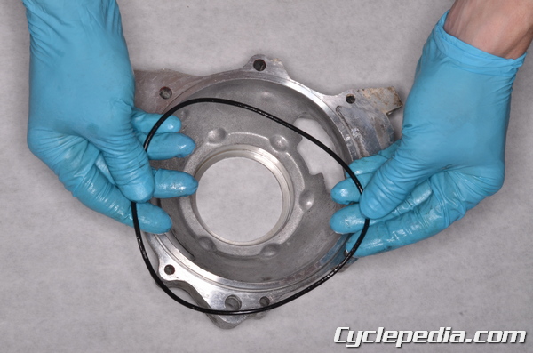
Install a new O-ring onto the left differential case half. Coat the O-ring in grease.
Fit the left differential case onto the right.
Apply a non-permanent thread locking agent (Blue Loctite) to the threads of the differential case bolts.
Check the backlash as the differential case bolts are tightened. If the backlash disappears stop tightening the bolts and address the problem. See the Differential Inspection topic for more information.
Install the four differential case bolts and tighten them to specification with a 10 mm and 8 mm socket.
Front Final Gear Case Bolts
(M6): 9.8 N-m, 1.0 kgf-m, 87 in-lb
(M8): 24 N-m, 2.4 kgf-m, 17 ft-lb
Install the differential left cover dowel pins and a new gasket.
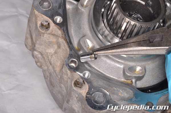
Install the six steel balls.
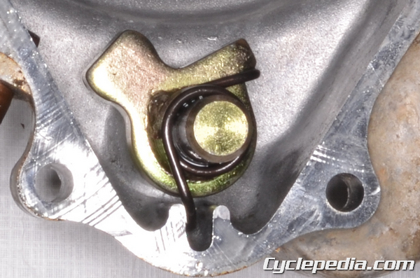
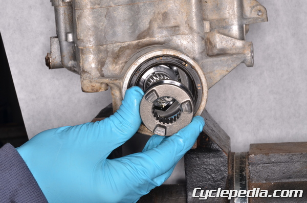
Install the cam plate so that its notch faces up.
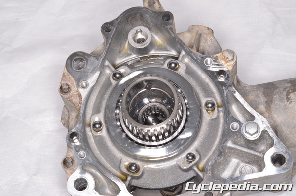
Install the inner needle bearing.
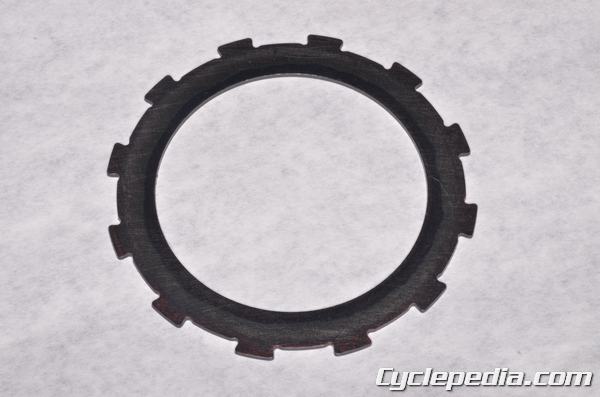
Install the inner clutch disc onto the inner needle bearing. Make sure the inner disc is the correct size to fit the clutch pack. See the Differential Inspection topic for more information.
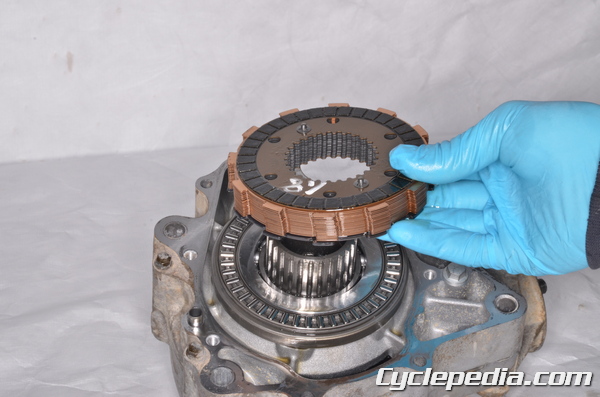
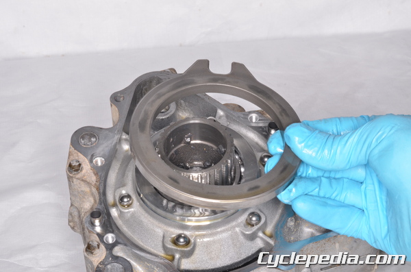
Install the clutch pack. The side with the clips should face to the left.
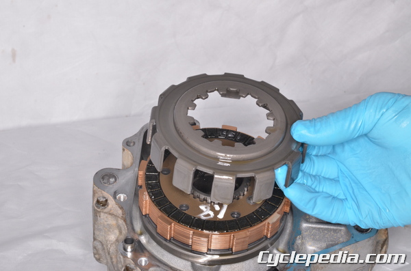
Install the differential disc basket.
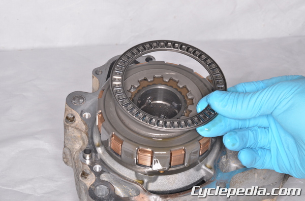
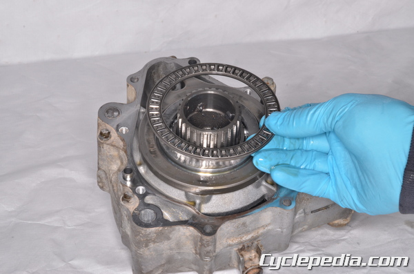
Install the outer needle bearing.
Install the outer disc.
Lubricate the differential control shift shaft with oil and install it into the left differential cover.
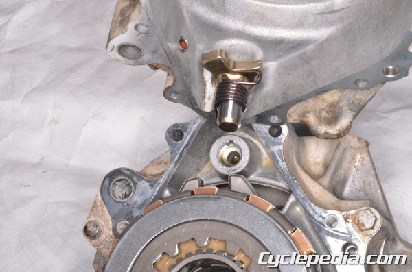
Rotate the shaft counterclockwise and fit the tab into the cam plate as the left differential cover is installed. Guide the shaft in to its hole.
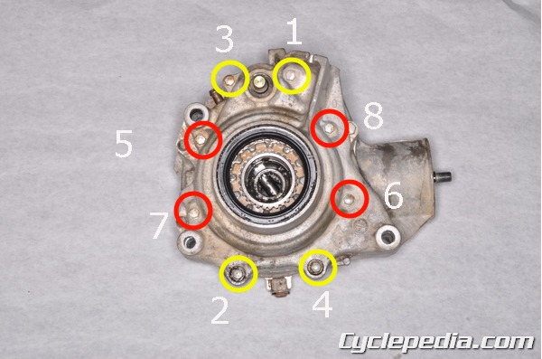
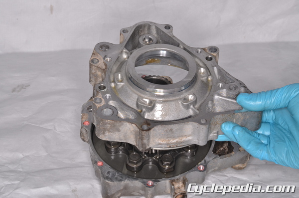
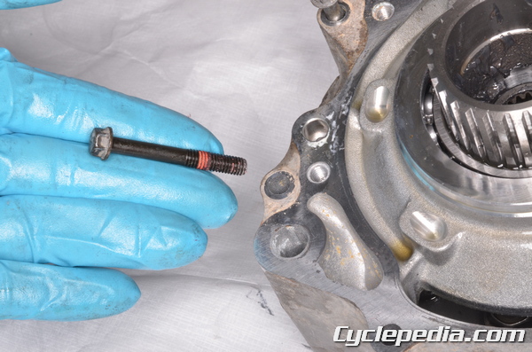
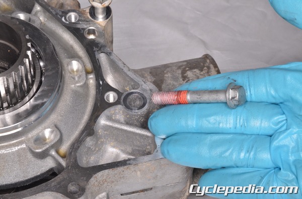
Install the left differential cover and its eight bolts. The bolts marked 1 – 4 are longer than the 5 – 8 bolts. Apply a non-permanent thread locking agent (Blue Loctite) to the threads of the longer bolts.
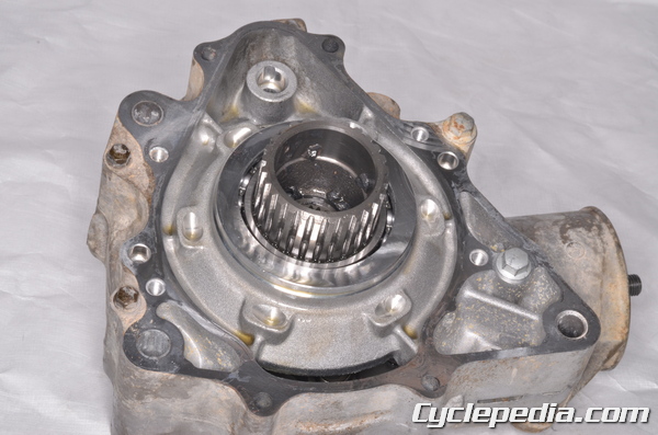
Tighten the left differential cover bolts to specification with an 8 mm socket.
Front Final Gear Case Left Cover Bolts (M6): 9.8 N-m, 1.0 kgf-m, 87 in-lb
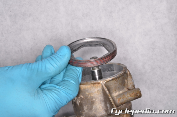
Install the coupling seal. Drive the seal into place with a suitable bearing driver that is the same outside diameter as the seal.
Special Tool- Oil seal and Bearing Driver Dia. 70: 57001-1506
Lubricate the lips of the oil seals with grease. Lubricate the splines and dogs of the shifter and the splines and slots of the coupling piece with molybdenum disulfide grease.
Install the shifter onto the pinion shaft.
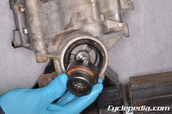
Install the coupling piece onto the pinion shaft.
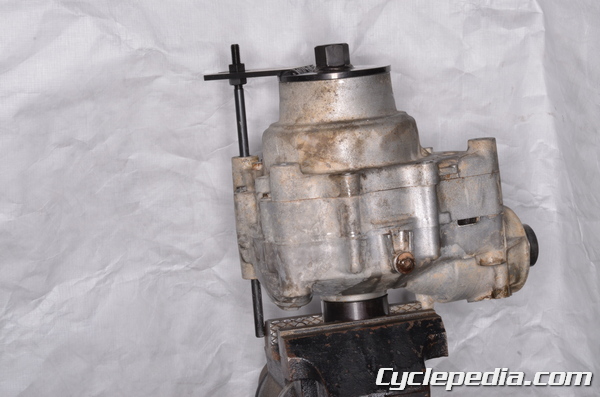
Support the front differential in a vise with the special tools.
Special Tool – Gear Holder and Socket Wrench Hex 24: 57001-1489
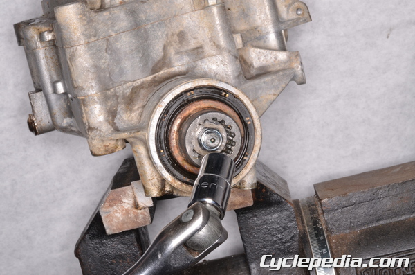
Install the coupling nut and washer. Tighten the front differential coupling nut to specification with a 14 mm socket.
Front Final Gear Case Coupling Nut
(M8) [2002]: 20 N-m, 2.0 kgf-m, 14 ft-lb
(M10) [2003 and Newer]: 25 N-m, 2.5 kgf-m, 18 ft-lb
Install the 2WD / 4WD actuator. See the Actuators topic for more information.
Install the differential. See the Front Differential topic for more information.