
 Like this Manual?
SAFETY FIRST: Protective gloves and eyewear are recommended at this point.
Removal
Remove the front wheels and hubs. See the Wheels and Hubs topic for more information.
Remove the front brake calipers. See the Front Caliper topic for more information.
The 2005 and older models came with knuckles that have a separate lower ball joint that was mounted to the suspension arm with a snap ring. If you have this type of knuckle check with Kawasaki to see if this should be replaced with the newer style in a recall.
Support the front of the frame with a jack.
Free the front brake hose from the steering knuckle.
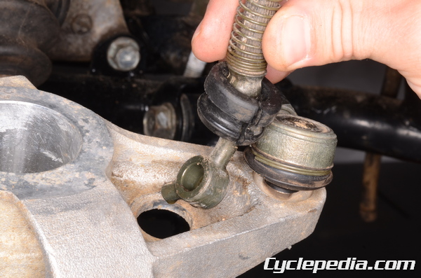
Remove the cotter pin from the outer tie-rod end bolt. Loosen the outer tie-rod nut with a 17 mm socket.
Free the outer end of the tie-rod from the knuckle.
Hold the clamp bolts with a 14 mm socket.
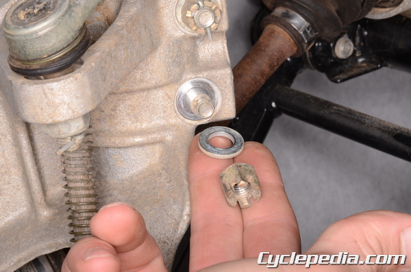
Remove the cotter pins from the front shock absorber clamp nuts. Remove the nuts and washers with a 14 mm socket.
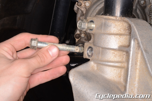
Remove the bolts.
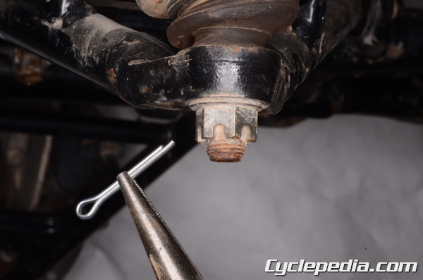
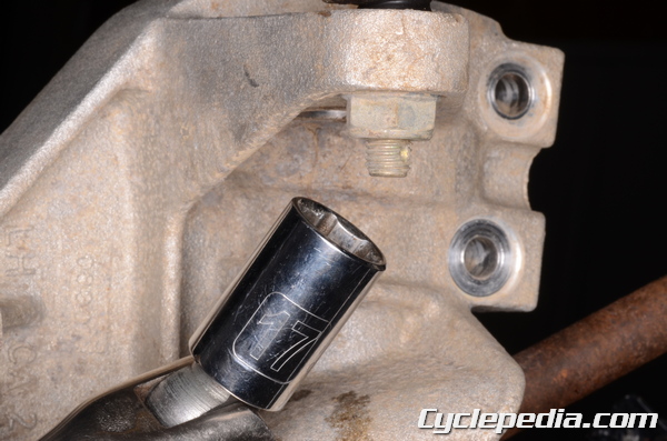
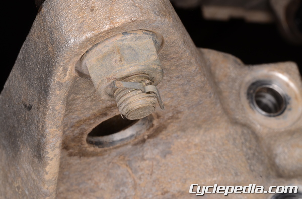
Remove the cotter pin from the knuckle ball joint nut.
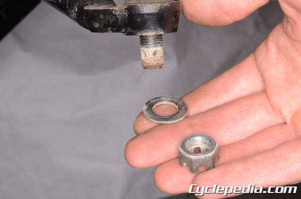
Loosen knuckle ball joint nut with a 17 mm socket. Remove the nut and the washer.
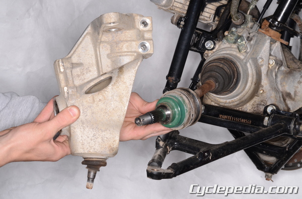
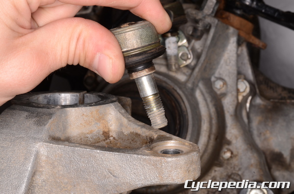
Lift the knuckle ball joint out of the suspension arm and free the front axle from the knuckle.
To remove the front axle see the Front Axles topic.
Inspection
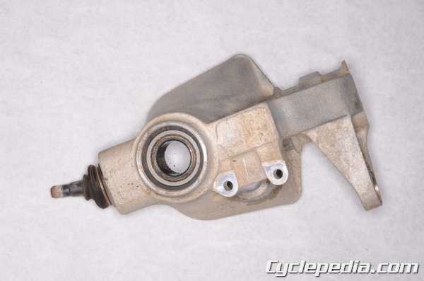
Inspect the knuckle for damage.
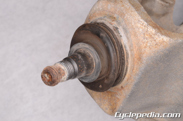
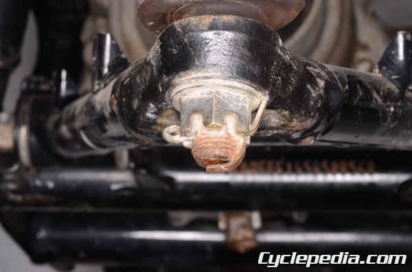
Inspect the knuckle ball joint boot for damage and leaks. Move the ball joint by hand and make sure it moves smoothly. If the ball joint or boot is in poor condition the knuckle must be replaced as a while.
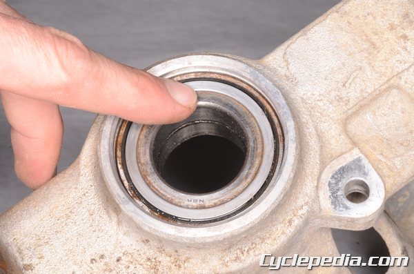
Check the knuckle bearing by turning it by hand. If the bearing is rough or has excessive play in the knuckle it will need to be replaced.
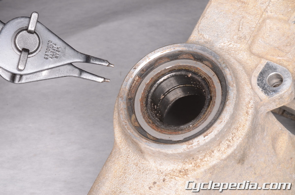
Remove the snap ring with snap ring pliers.
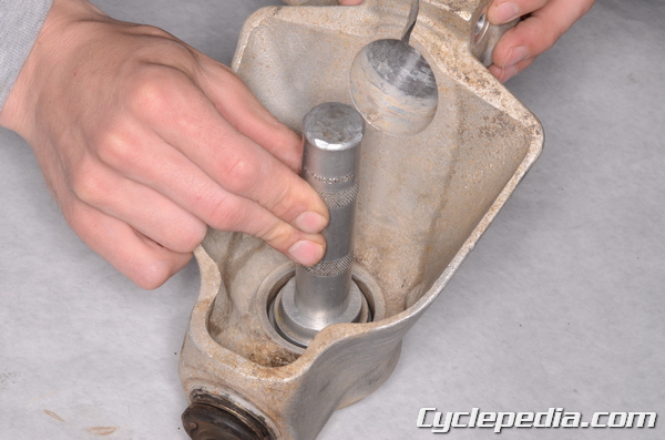
Drive out the bearing from the inside of the knuckle.
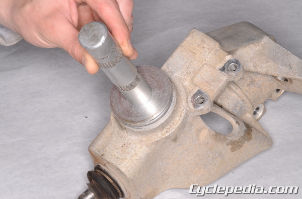
Drive in the new bearing with a suitable bearing driver that is the same outside diameter as the bearing. Make sure the bearing is fully seated in the knuckle. The markings on the bearing should face out.
Special Tool – Bearing Driver Set: 57001-1129
Install a new snap ring into the groove with snap ring pliers.
Installation
Clean the part of the knuckle ball joint where it will fit into the suspension arm with a cleaning solvent and rag. Also, clean the mating surface in the suspension arm in the same manner.
Install the steering knuckle onto the drive shaft. Fit the knuckle ball joint into the suspension arm. Fit the shock absorber into the knuckle.
Install the washer and nut onto the knuckle ball joint. Tighten knuckle ball joint nut to specification with a 17 mm socket.
Steering Knuckle Joint Nut (2006 – 2011): 29 N-m, 3.0 kgf-m, 21 ft-lb
Install a new cotter pin and bend it to secure the nut.
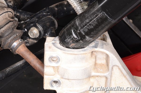
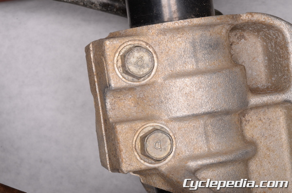
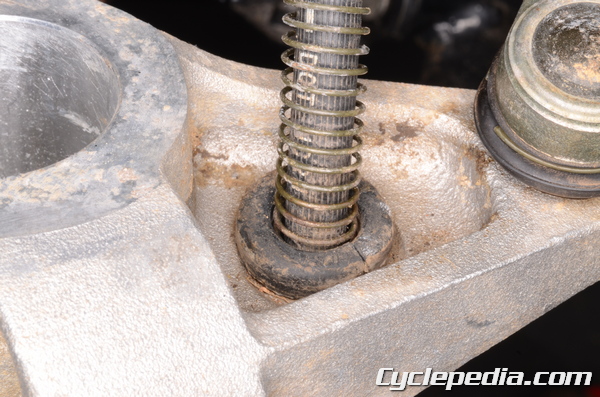
Fit the shock absorber into the knuckle so that the recess on the bottom of the shock absorber body lines up with the lower bolt hole of the shock absorber clamp on the knuckle.
Insert the two shock absorber clamp bolts from the front. The lower bolt must pass through the recess on the shock body.
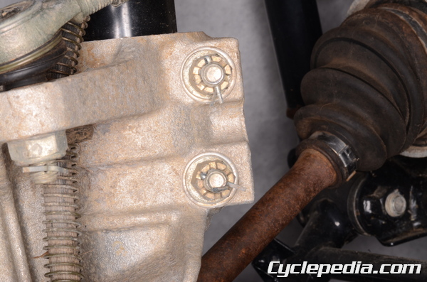
Place the washers and nuts on the clamp bolts. Hold the clamp bolts with a 14 mm socket and tighten the nuts to specification with a 14 mm socket.
Front Shock Absorber Clamp Nuts: 42 N-m, 4.3 kgf-m, 31 ft-lb
Install the new cotter pins and secure the front shock absorber clamp nuts.
Fit the outer end of the tie rod into the knuckle. Install the outer tie-rod nut and torque it to specification with a 17 mm socket.
Tie-rod End Nuts: 42 N-m, 4.3 kgf-m, 31 ft-lb
Install the new cotter pin into the outer tie-rod end bolt and bend it to secure the nut.
Fit the front brake hose and grommet into the steering knuckle.
Install the front brake calipers. See the Front Caliper topic for more information.
Install the front wheels. See the Wheels and Hubs topic for more information.
Check the toe-in. See the Toe-In Adjustment topic for more information.