
 Like this Manual?
SAFETY FIRST: Protective gloves and eyewear are recommended at this point.
Make sure the rubber damper is in place on the engine guard.
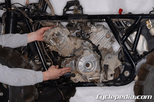
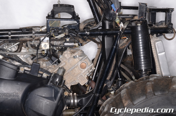
Fit the engine into the left side of the frame.
Connect the rear propeller shaft to the engine as the engine is moved backwards.
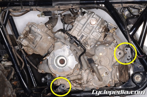
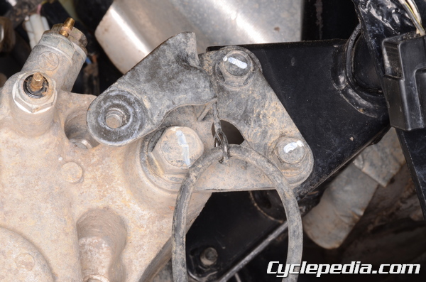
Install the two engine mounting brackets with two bolts each and the front and rear engine mounting bolts. Insert the engine mounting bolts from the left side.
Tighten the engine mounting bracket bolts to specification with a 12 mm socket.
Engine Mounting Bracket Bolts
2002 – 2003: 23 N-m, 2.3 kgf-m, 17 ft-lb
2005 – 2011, 700cc: 32 N-m, 3.3 kgf-m, 24 ft-lb
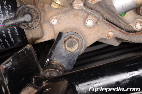
Tighten the rear engine mounting bolt to specification with a 17 mm socket.
Engine Mounting Bolt
2002 – 2003: 59 N-m, 6.0 kgf-m, 43 ft-lb
2005 – 2011, 700cc: 62 N-m, 6.3 kgf-m, 46 ft-lb

Thread on the front engine mounting nut.
Hold the front engine mounting bolt with a 17 mm socket while tightening the nut to specification with a 17 mm socket.
Engine Mounting Bolt/Nut
2002 – 2003: 59 N-m, 6.0 kgf-m, 43 ft-lb
2005 – 2011, 700cc: 62 N-m, 6.3 kgf-m, 46 ft-lb
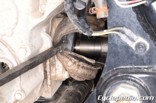
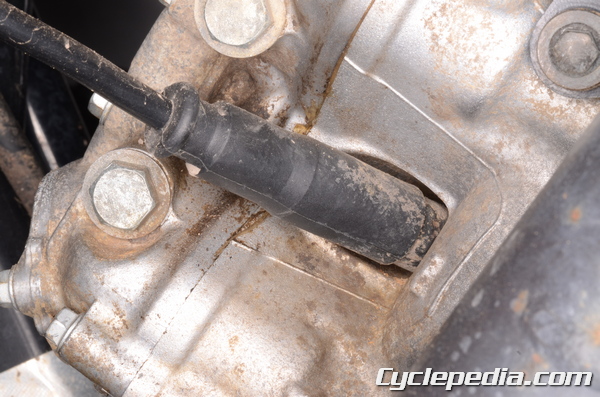
Fit the rear propeller shaft boot into place.
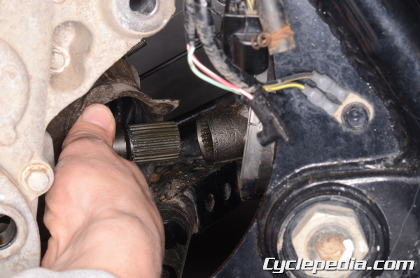
Install the rear propeller shaft boot clamp and tighten it securely. Clean off the old grease from the front propeller shaft splines. Inspect the splines for wear and damage and replace the parts as needed. Lubricate the splines with fresh molybdenum disulfide grease.
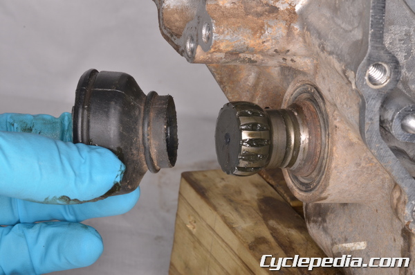
Place the rubber boot on the front of the output driven bevel gear shaft if it was removed. When installing the rubber boots- the O-ring clamps must land in the grooves on the shaft to be secure.
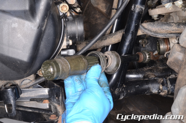
Install the propeller shaft to the engine and pull it back. Fit the front of the shaft into the front differential.
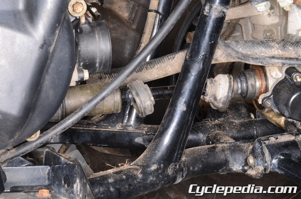
Slide the rubber covers into place.
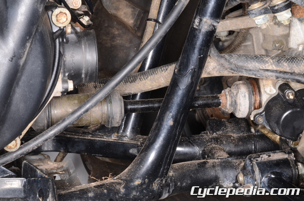
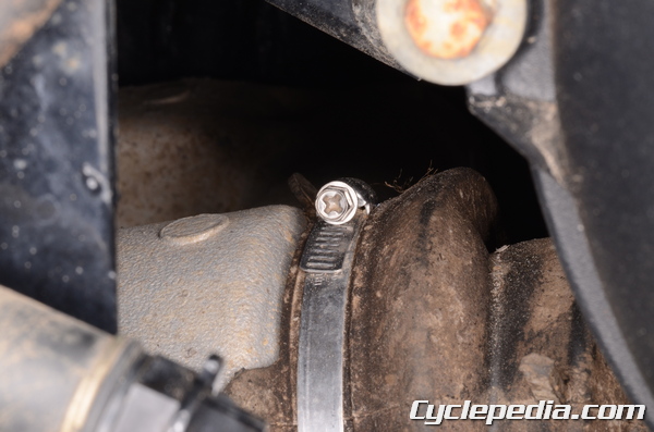
Secure the rubber covers with the O-ring clamps.
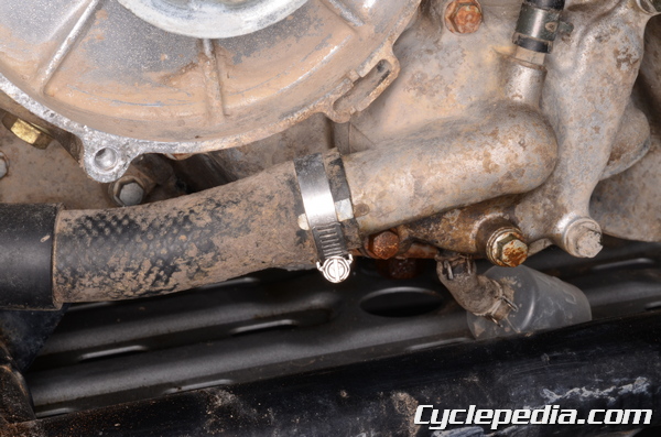
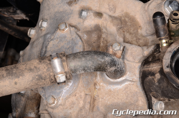
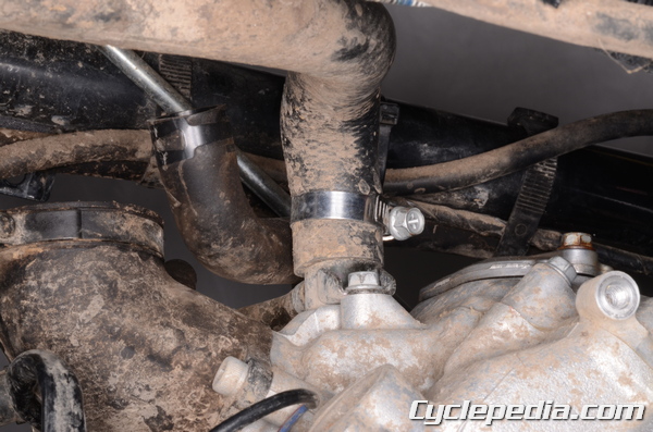
Connect the coolant hoses to the cylinder heads and the water pump. Tighten the coolant clamps securely.

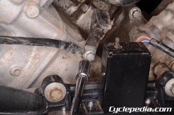
Connect the shift lever linkage to the engine. Install the shift lever tie-rod nut and torque it to specification with a 12 mm socket.
Tie-Rod End Nut: 20 N-m, 2.0 kgf-m, 14 ft-lb
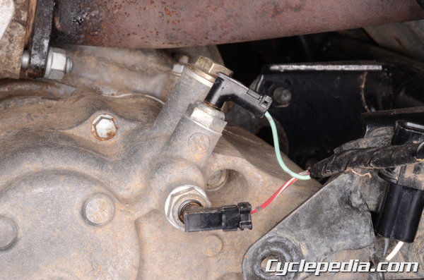
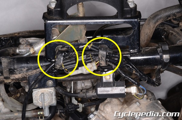
Plug in the neutral and reverse switch connectors.
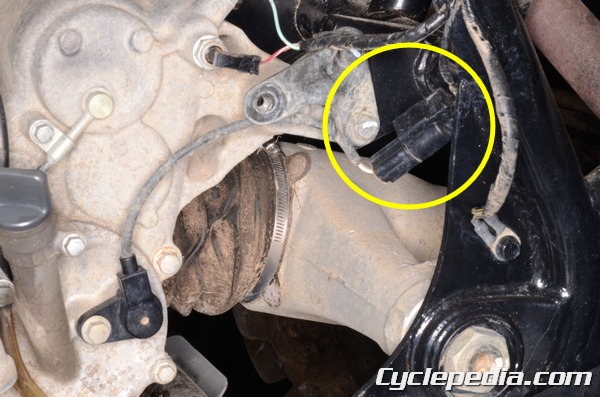
Plug in the forward / reverse detecting sensor connector.
Plug in the speed sensor connector.
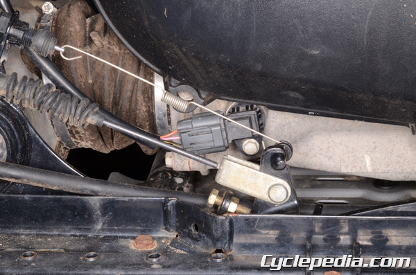
Plug in the engine braking actuator connector.
Install the engine ground and clamp. Tighten the bolt securely with and 8 mm socket.
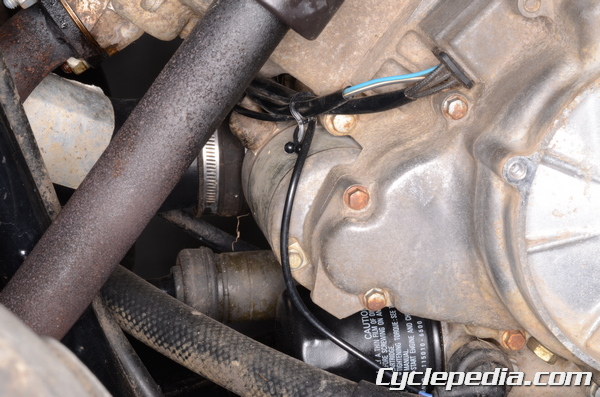
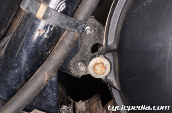
Route the oil pressure switch wire up from the bottom left of the engine to the right side of the frame.
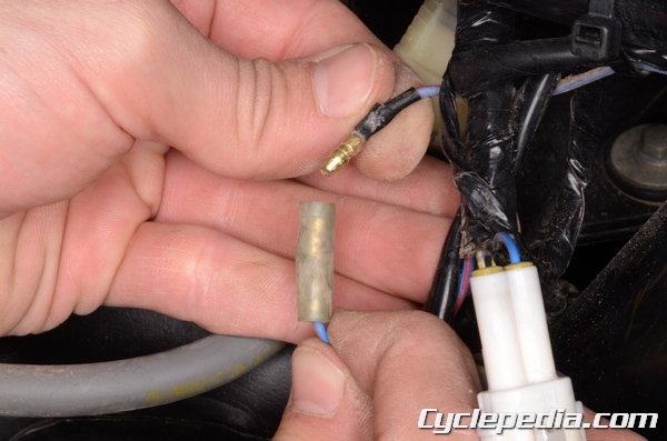
Plug in the oil pressure switch bullet connector.
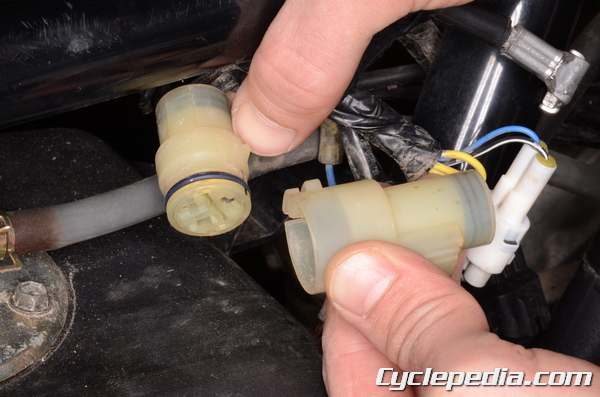
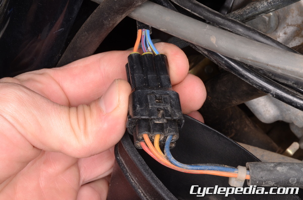
Route alternator wires around the front of the engine and up to the right side of the frame as with the oil pressure switch. Plug in the alternator 3-pin connector.
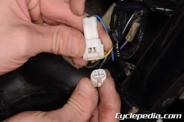
Plug in the 2-pin pickup coil/crank position sensor connector.
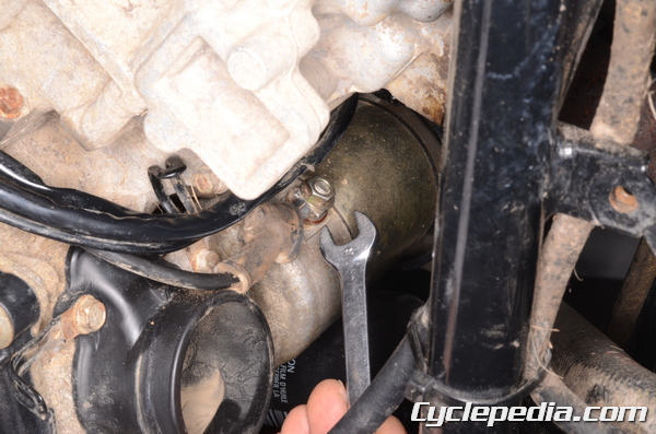
Install the starter motor lead to the starter motor. Tighten the terminal nut to specification with a 10 mm wrench.
Starter Motor Terminal Nut: 4.9 N-m, 0.5 kgf-m, 43 in-lb
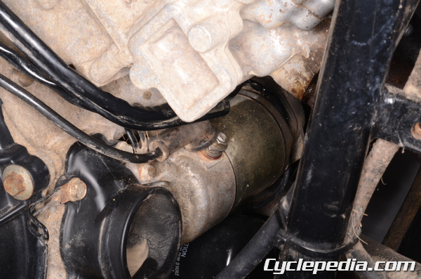
Move the rubber cap over the terminal, and secure the wires coming around the front of the engine with the clamp.
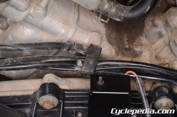
Secure the wires routing along the right side of the engine with the clamp.
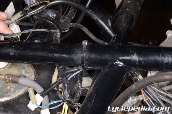
Install the wire band to secure the wires to the right side of the frame.
Install the spark plug caps to the plugs.

Plug in the dive belt failure detector 2-pin connector.
Close the wire clamp to secure the wires.
Install the CVT air intake duct joint and air intake.
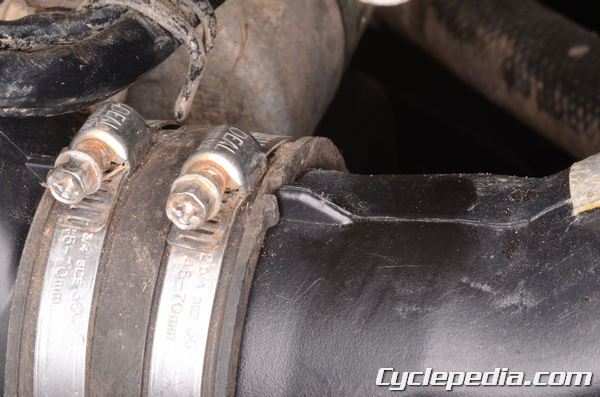
The joint groove must fit around the projections. Tighten the clamps securely.
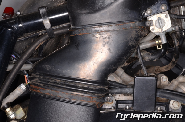
Install the air duct with both air duct clamps.


Tighten the air duct clamp screws securely with a #2 Phillips screwdriver.
Install the footrests. See the Footrests topic for more information.
Install the front ignition coil from the left side of the frame. See the Ignition System topic for more information.
Install the carburetors. See the Carburetor Installation topic for more information.
Install the exhaust system. See the Exhaust System topic for more information.
Fill the engine oil. See the Engine Oil topic for more information.
Fill and bleed the coolant. See the Coolant topic for more information.
Install the rear fender. See the Rear Fender topic for more information.
Install the front inner fender. See the Front Fender topic for more information.