
 Like this Manual?
The ignition timing is set at the factory and is not adjustable. To troubleshoot the ignition system, you will need a digital multimeter and a Peak Voltage Adapter (PVA). Perform the following checks. Before performing any tests make sure the electrical connections are not loose or corroded. Also, make sure the engine has good compression, the engine kill switch is in the run position, the main fuse is not blown, and the battery has a full charge.
Turn the ignition switch to the OFF position before unplugging any electrical components.
SAFETY FIRST: Protective gloves and eyewear are recommended at this point.
Warning: Do not touch the spark plug or spark plug wire while cranking or running the engine as this can result in a severe shock.
Special Tool – Hand Tester: 57001-1394
Electrical Connections
Make sure all electrical connections are good. There must not be open, loose, or rusted connections.
Make sure the battery is fully charged and the fuses are in good condition. See the Battery and Fuses and Relays topics for more information.
Troubleshooting
Spark Check
Check the spark plug to see if it is the correct type and gapped properly. If the spark plug is black and fouled, replace it. See the Spark Plugs topic for more information.
Connect a known good spark plug to the cap and ground the plug to the engine. There should still be a spark plug installed in the cylinder head.
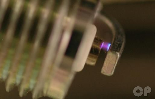
Push the engine start button and check that the plug will spark. Repeat the process with the other spark plug. If the plug does not spark go through the following procedures to find the problem.
Ignition Coil
Removal
Remove the front left inner cover for the front ignition coil. See the Inner Covers topic for more information.
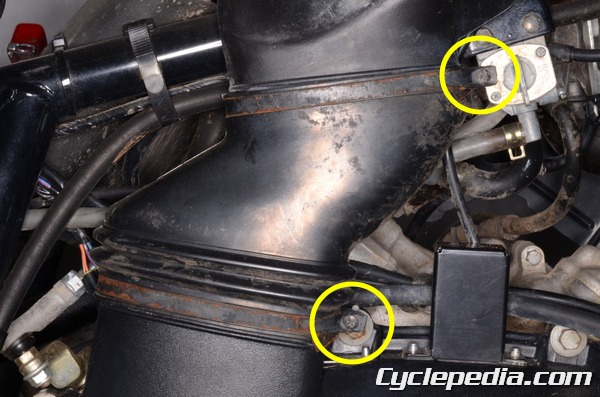
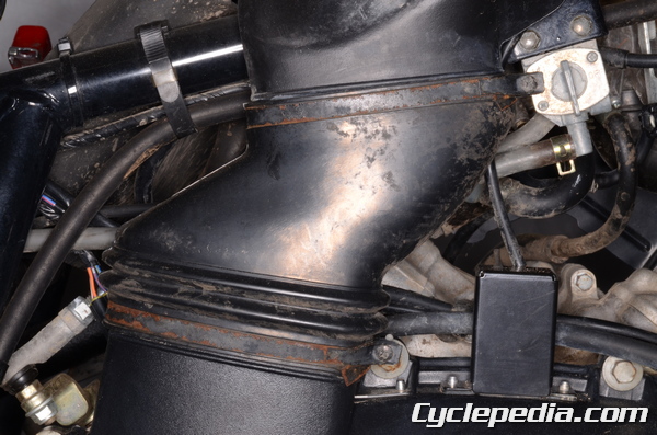
To remove the rear ignition coil the converter air duct must be removed. Loosen the air duct clamp screws with a #2 Phillips screwdriver.
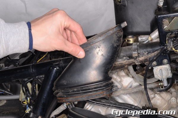
Remove the air duct.
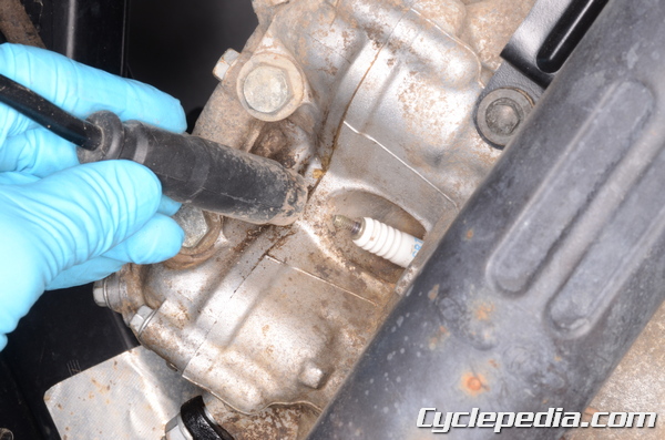
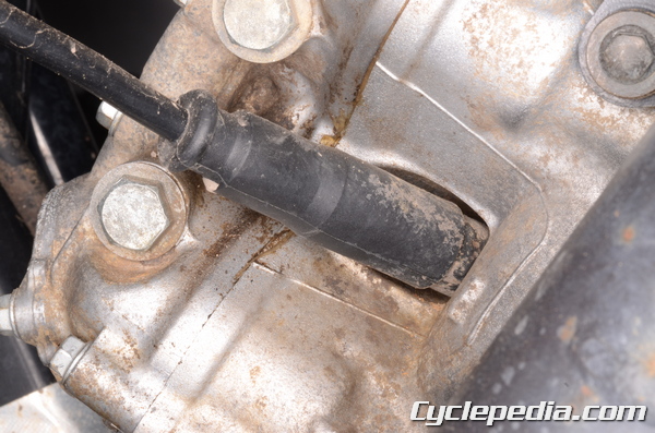
Pull the spark plug cap off of the spark plug.
Remove both ignition coils in the same manner. The rear ignition coil is mounted to the right side of the frame and the front ignition coil is mounted to the left.
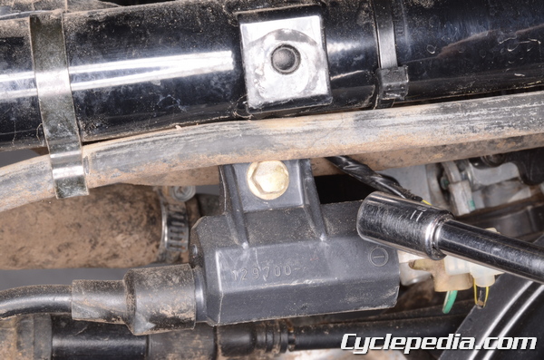
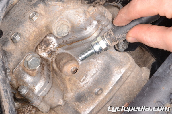
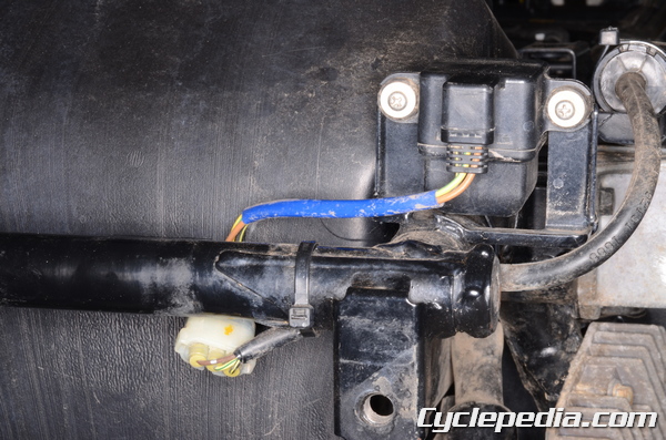
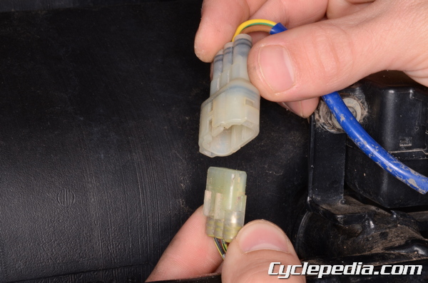
Unplug the ignition coil leads. Remove the ignition coil mounting bolt with an 8 mm socket.
Remove the ignition coil. Free the spark plug wire from the two wire bands for the rear ignition coil
Installation
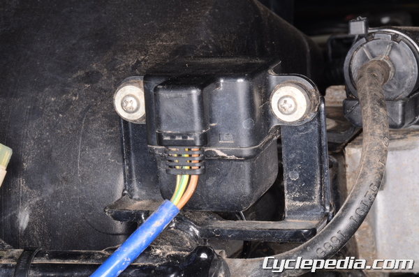
Fit the ignition coil into place. Plug in the ignition coil lead connectors. The ignition coil terminals are marked for positive and negative. Connect the leads as indicated.
| Ignition Coil Terminal | Wire Color |
| Front + | green/white |
| Front – | black/yellow |
| Rear + | blue/white |
| Rear – | black/yellow |
Insert the ignition coil mounting bolt. Tighten the mounting bolt securely with an 8 mm socket.
Install the spark plug caps onto the spark plugs. Secure the rear spark wire to the frame with the two wire bands.
Install the air duct.


Tighten the air duct clamp screws securely with a #2 Phillips screwdriver.
Install the front left inner cover for the front ignition coil. See the Inner Covers topic for more information.
Ignition Coil Inspection
Primary Winding Resistance
Set the multimeter to read ohms of resistance (Ω).
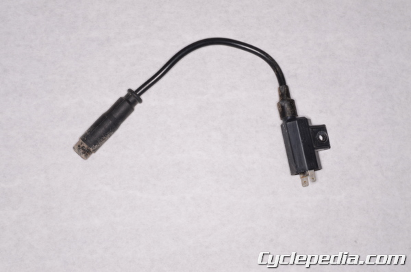
Touch one of the meter leads to one of the blade connectors and the other meter lead to the other blade. Polarity of the meter leads does not matter. Replace the ignition coil if your measurement does not meet specification.
Primary Winding Resistance: 0.09 ~ 0.13 Ω
Secondary Winding Resistance
Set the multimeter to read ohms of resistance (kΩ).
Remove the plastic spark plug cap from the spark plug wire by unscrewing it.
Touch one of the meter leads to the inside of the spark plug wire and touch the other meter lead to the negative blade connector. Polarity of the meter leads does not matter. Replace the ignition coil if your measurement does not meet specification.
Secondary Winding Resistance: 3.8 ~ 5.8 kΩ
Primary Peak Voltage
Check the ignition coil peak voltage with the ignition coil leads connected and make sure the battery is fully charged.
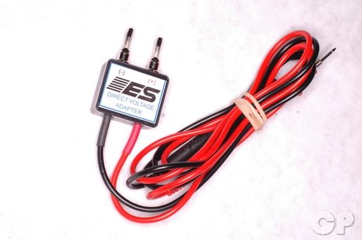
Note: In order to test peak voltage, a Peak Voltage Adaptor (PVA) must be used. PVAs can be found at most automotive or electrical stores.
Special Tools
Needle Adapter Set: 57001-1457
Peak Voltage Adapter: 57001-1415
Type: KEK-54-9-B
Use the needle adapter set to allow the meter lead to reach the ignition coil lead wire while it is plugged in. The green/white wire needs to be tested for the front cylinder and the blue/white wire for the rear. Touch the negative PVA lead to the ignition coil wire via the needle adapter set. Touch the positive PVA lead to an engine ground.
With a plug installed in the head remove the spark plug cap a place a known good plug in the cap. Ground the plug in the cap to the frame or cylinder head cover bolt.
Set the multimeter to read voltage (VDC 100+) when using the Peak Voltage Adaptor or follow the directions if different.
Turn the ignition switch on and place the kill switch in the run position.
Press the starter button for 4 to 5 second and measure the peak voltage. Measure several times and go by the highest reading. Repeat the test for the other cylinder.
Primary Peak Voltage: 100 V or more
Crankshaft Sensor (Pickup coil 2002 – 2003)
To remove and install the crankshaft sensor see the Alternator topic.
Resistance
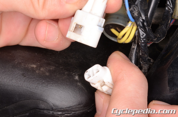
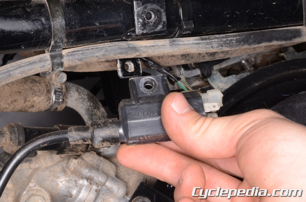
The crankshaft position sensor connector is located on the right side of the frame just forward of the fuel tank. Disconnect the crankshaft sensor 2-pin connector.
Set the multimeter to read ohms of resistance (Ω X 10).
Measure the resistance on the sensor side of the connector.
Crankshaft Sensor Resistance: 110 ~140 Ω
Peak Voltage
Remove the spark plug caps from the plugs, but leave the plugs in the heads.
Set the multimeter to read voltage (VDC 10) when using the Peak Voltage Adaptor or follow the directions if different.
Special Tools
Peak Voltage Adapter: 57001-1415
Type: KEK-54-9-B
Connect the black PVA lead to the negative multimeter lead and the red PVA lead to the positive multimeter lead.
Connect the PVA leads to the wire terminals as indicated. Measure the peak voltage five times or more.
| Item | Peak Voltage | PVA + | PVA – |
| Pickup coil peak voltage [2002 – 2003] | 3.6 V or more | yellow | green/white |
| Crankshaft sensor peak voltage [2005 – 2011] | 2 V or more | black/white | blue |
| Crankshaft sensor peak voltage [700 models] | 2 V or more | blue | black/white |
Vehicle Down Sensor (Tip-Over Sensor)
When the vehicle exceeds a 60° to 70° lean angle or rolls over the tip-over sensor will stop the engine via the ignition and the electric fuel pump where applicable.
Removal
Remove the rear fender. See the Rear Fender topic.
the tip-over sensor is located on the very back of the frame on the right side.
Unplug the three pin tip-over sensor connector.
Remove the two mounting screws with a #2 Phillips screwdriver.
Installation
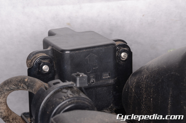
Fit the tip over sensor into place and install the two mounting screws. Make sure the sensor is upright as indicated by the arrow.
Plug in the three pin tip-over sensor connector.
Install the rear fender. See the Rear Fender topic.
Testing
Unplug the three pin tip-over sensor connector.
Set the digital multi meter to read voltage (VDC).
12V Circuit
Touch the positive meter lead to the brown wire terminal on the harness side of the connector and the negative meter lead to the black/yellow wire terminal on the harness side of the connector.
Turn the ignition switch to the ON position and measure the voltage. The battery voltage should show. Turn the ignition switch to the OFF position.
If the battery voltage does not show inspect the following.
- Main Fuse 30A – Fuses and Relays topic
- Ignition Switch – Switches topic
- Wiring Harness – sensor power wires black/yellow and/or brown
5V Circuit
Touch the positive meter lead to the yellow/green wire terminal on the harness side of the connector and the negative meter lead to the black/yellow wire terminal on the harness side of the connector.
Turn the ignition switch to the ON position and measure the voltage. There should be around 5 V showing. Turn the ignition switch to the OFF position.
If the voltage does not show correctly there is a problem in the wiring harness with the black/yellow and/or yellow/green wire. Possibly the igniter box could be faulty.
Output Voltage
The output voltage must be tested with the sensor connected, but free of the frame.
Touch the positive meter lead to the yellow/green wire and the negative meter lead to the black/yellow wire. Support the sensor so that it is level and its arrow mark is facing up. Turn the ignition switch to the ON position and measure the voltage.
There should be 0.4 – 1.4 V with an upright sensor.
Rotate the sensor 60° to 70° to the right or left. The voltage should increase to 3.7 – 4.4 V. Replace the vehicle down sensor if the voltage is out of specification.
Igniter Box
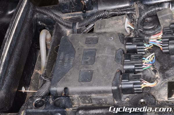
The igniter box is located under the seat. See the Seat topic for more information.
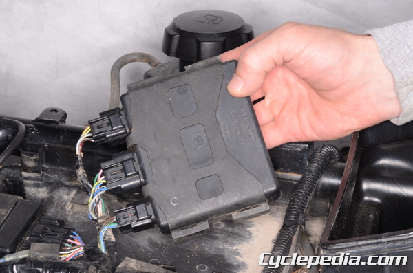
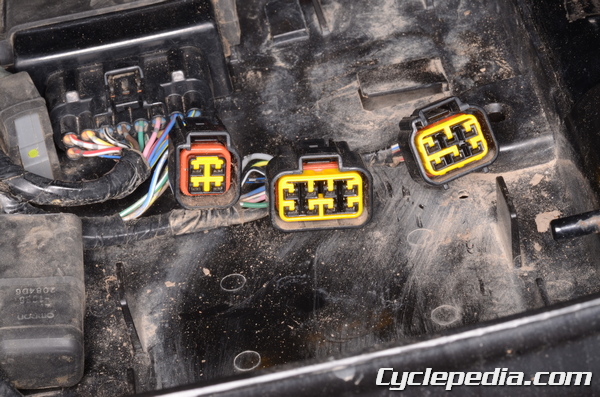
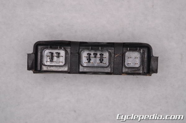
Replace the igniter only as a last resort. Inspect and test all problem related components and wires in the wiring harness before replacing the igniter.