
 Like this Manual?
SAFETY FIRST: Protective gloves and eyewear are recommended at this point.
Removal
Remove both cylinders in the same manner.
Remove the cylinder head. See the Cylinder Heads topic for more information.
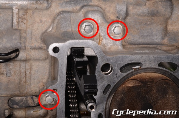
Remove the three cylinder bolts with an 8 mm socket.
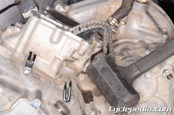
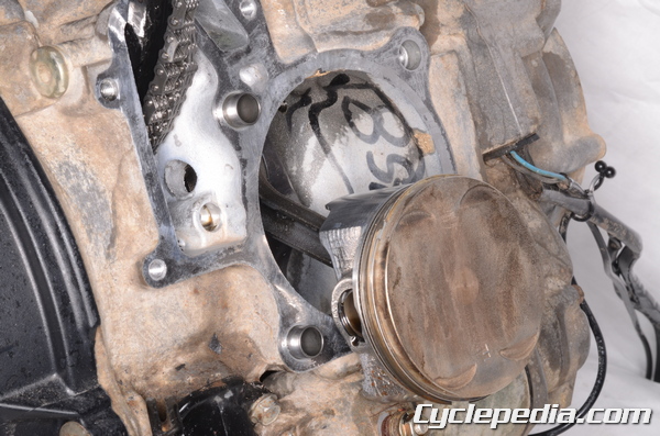
Gently tap the cylinder with a rubber mallet to free it from the crankcase.
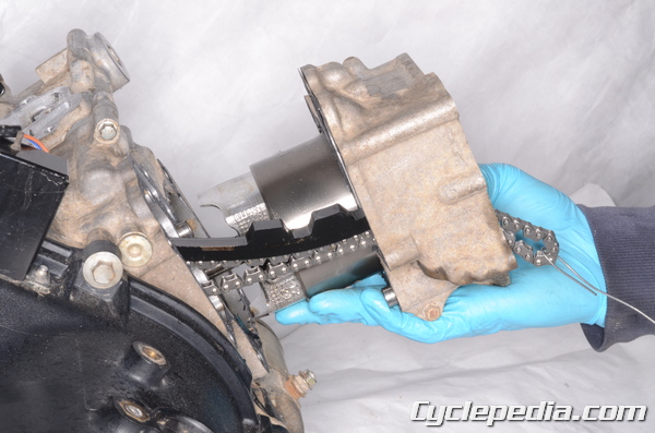
Lift the cylinder up and off of the crankcase and piston. Guide the cam chain through its opening in the cylinder if it is still installed. Make sure the cam chain and dowel pins do not fall into the crankcase.
Remove the base gasket.
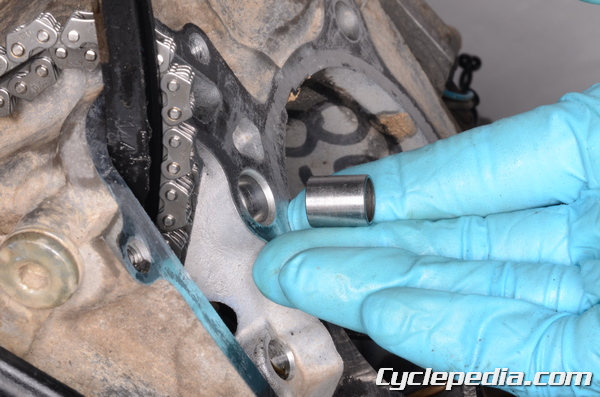
Remove the two dowel pins.
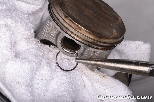
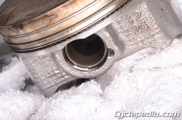
Place a clean shop towel around the base of the piston to prevent any parts or debris from falling into the crankcase. Remove the piston pin clip with a pick or needle nose pliers. Discard the piston pin clips. Rotating the end of the clip to the access gap will make this easier.
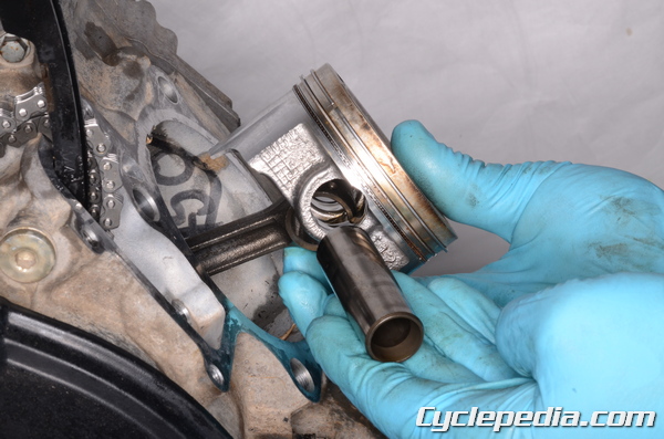
Remove the piston pin. Use a piston pin puller if the pin is difficult to remove.
Special Tools
Piston Pin Puller Assembly: 57001-910
Piston Pin Puller Assembly: 57001-1211
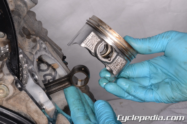
Remove the piston.
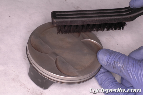
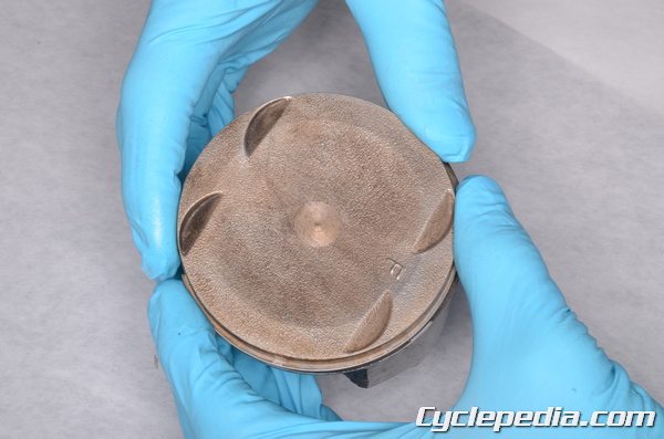
Clean the carbon build up off of the piston with a stiff bristled plastic brush. Never use a wire brush to clean a piston.
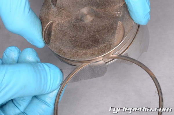
Spread the piston rings and lift them off opposite the gap. Spread the rings the minimum amount during removal. The rings can be easily damaged.
There is a top ring, 2nd ring, and an oil expander ring with two side rails.
Clean out the ring grooves. You can use an old ring to scrape out any built up carbon in the grooves.
Inspection
Cylinder Bore
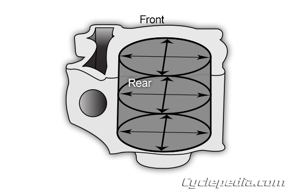
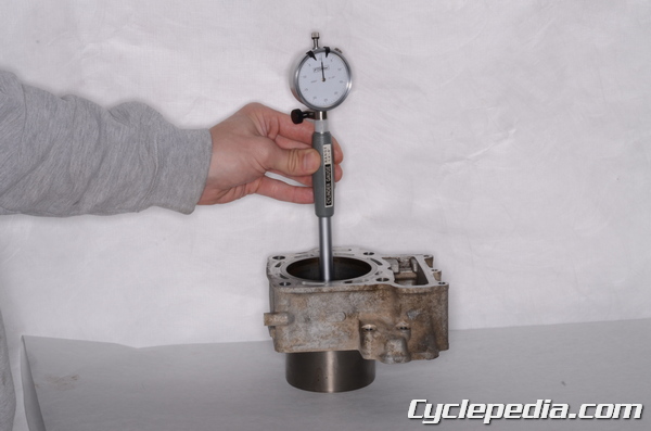
Inspect the cylinder and measure front-to-back and side-to-side at three different height levels with a dial bore gauge or cylinder gauge set.
Measure the cylinder at 10 mm (0.4 in.) down from the top, 60 mm (2.4 in.) down from the top, and 20 mm (0.8 in.) up from the bottom.
Cylinder Diameter
KVF650: 79.994 – 80.006 mm (3.1494 – 3.1498 in.)
Service Limit: 80.09 mm (3.153 in.)
KVF700: 81.994 – 82.006 mm (3.2281 – 3.2286 in.)
Service Limit: 82.10 mm (3.232 in.)
Difference Between Any Two Measurements:
Standard: < 0.1 mm (0.0004 in.)
Service Limit: < 0.5 mm (0.0020 in.)
If the cylinder is out of specification or damaged it should be repaired by a qualified machine shop or replaced.
Piston Diameter
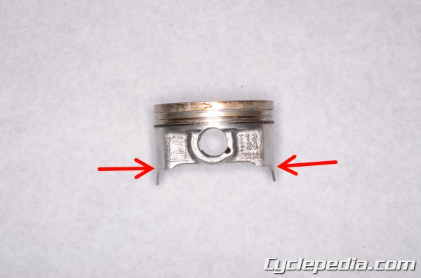
Measure the diameter of the piston 5 mm (0.2 in) up from the bottom of the skirt at a 90° angle to the piston pin. Measure the piston with a micrometer. Replace the piston if the measurement is out of specification. Check the piston for wear and extreme discoloration.
Piston Diameter
KVF650: 79.949 – 79.964 mm (3.1476 – 3.1481 in.)
Service Limit: 79.80 mm (3.142 in.)
KVF700: 81.949 – 81.964 mm (3.2263 – 3.2269 in.)
Service Limit: 81.80 mm (3.220 in)
Piston to Cylinder Clearance
Subtract the diameter of the piston from the front-to-rear diameter measurement of the cylinder to calculate the piston-to-cylinder clearance. If the clearance is over the service limit use an oversized piston with rings and bore out the cylinder or replace both the cylinder and piston. Base the oversize cylinder bore on a measurement of the oversized piston to be used.
Piston/Cylinder Clearance: 0.030 – 0.057 mm (0.0012 – 0.0022 in.)
* Oversize Piston: 0.5
If just the piston is replaced the piston-to cylinder clearance can be slightly above the specification. Do not have the clearance below the specification.
Piston Ring to Groove Clearance
Check the ring to groove clearance with a feeler gauge. Make sure the ring is in the correct grove.
Piston Ring/Groove Clearance
Top: 0.040 – 0.080 mm (0.0016 – 0.0032 in.)
Service Limit: 0.18 mm (0.0071 in.)
Second: 0.030 – 0.070 mm (0.0012 – 0.0028 in.)
Service Limit: 0.17 mm (0.0067 in.)
Piston Ring Groove Width
Check the ring groove clearance with a feeler gauge.
Piston Ring Groove Width:
Top: 1.030 – 1.050 mm (0.0405 – 0.0413 in.)
Service Limit: 1.13 mm (0.0445 in.)
Second: 1.020 – 1.040 mm (0.0402 – 0.0409 in.)
Service Limit: 1.12 mm (0.0441 in.)
Piston Ring Thickness
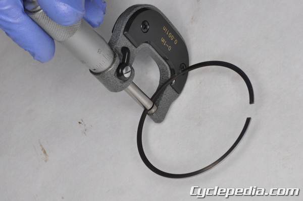
Measure the thickness of the top and second rings with a micrometer.
Piston Ring Thickness:
Top / Second: 0.97 – 0.99 mm (0.0382 – 0.0390 in.)
Service Limit: 0.9 mm (0.035 in.)
Piston Ring End Gap
Insert the top ring into the cylinder. Push the top ring in the cylinder about an inch. Use the piston to push in the ring to keep it square with the cylinder.
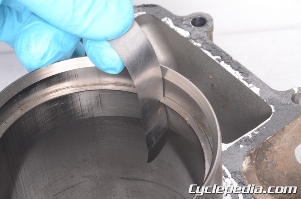
Measure the ring gap with a feeler gauge. Repeat this procedure with second ring and oil side rails.
Piston Ring End Gap:
Top: 0.20 – 0.30 mm (0.0079 – 0.0118 in.)
Service Limit: 0.60 mm (0.0236 in.)
Second: 0.30 – 0.45 mm (0.0118 – 0.0177 in.)
Service Limit: 0.75 mm (0.0295 in.)
Oil: 0.20 – 0.70 mm (0.0079 – 0.0276 in.)
Service Limit: 1.00 mm (0.0394 in.)
Assembly
Clean the piston ring grooves, and apply fresh engine oil to the piston rings. Spread the rings the minimum amount possible to install them.
Install the oil ring expander ring first then the steel rails above and below the oil ring. Install the oil expander ring so that the ends are close but not touching.
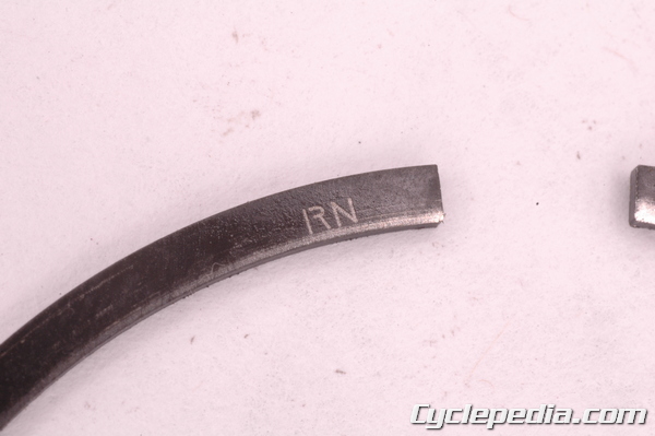
Install the second ring with the “RN” mark facing up. Its its inside chamfered edge should slope down from the top of the ring.
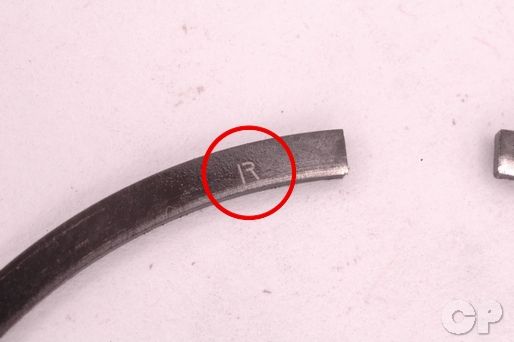
Install the top ring with the “R” mark facing up.
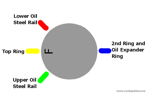
Position the piston ring end gaps.
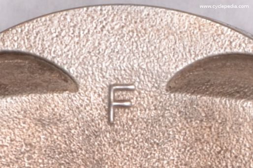
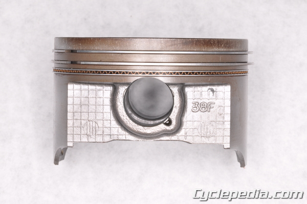
The F mark on the piston should face the front of the engine for both cylinders.
Lubricate the piston pin bore and piston pin with fresh engine oil.
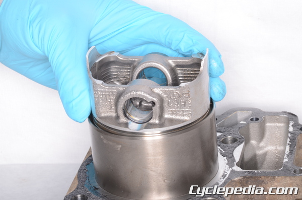
Fit the piston over the connecting rod with the F mark facing forward.
Insert the piston pin.
Place a clean shop towel around the base of the piston to prevent any parts or debris from falling into the crankcase. Install new piston pin clips into the grooves. Do not overly compress the clips during installation.
Rotate the ends of the clips so they are not in the access gap.
Make sure the cylinder mating area is clean. Install the two dowel pins and a new base gasket.
Coat the inside of the cylinder, piston rings, and piston in fresh engine oil. Lower the cylinder into place and guide the piston into the cylinder while you are compressing the rings with your fingers. Be careful to not damage the rings during this step. Bring the cam chain through the opening.
Install the three cylinder bolts and tighten them to specification with an 8 mm socket. Double check the torque of these bolts after the cylinder head has been installed.
Install the cylinder head. See the Cylinder Heads topic.