
 Like this Manual?
SAFETY FIRST: Protective gloves and eyewear are recommended at this point.
Removal
Remove the torque converter cover. See the CVT Cover topic for more information.
Remove the drive pulley and drive belt. See the Drive Belt topic for more information.
Disassembly

To disassemble the drive pulley you will need two special holder tools.
Special Tools
Drive and Driven Pulley Holder: 57001-1473
Drive and Driven Pulley Holder: 57001-1412
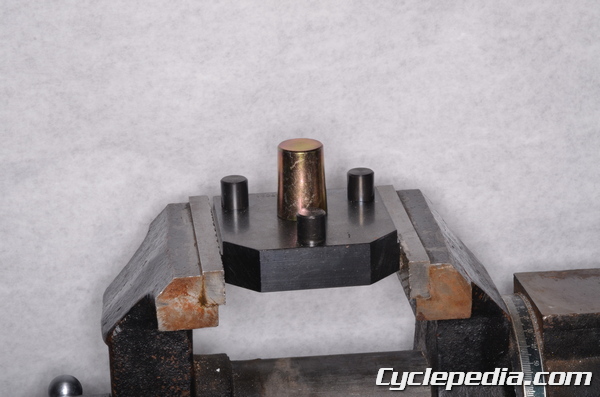
Thread the 57001-1412 into 57001-1473. Secure the holder tools in a vise so the holder plate protrudes 7 mm above the vise jaws.
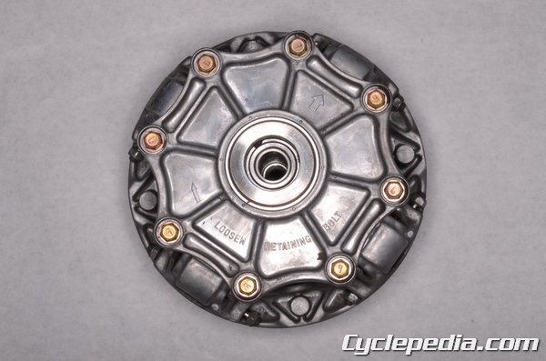
Set the drive pulley onto the holder so the side with the eight bolts faces up. The drive pulley cover is under spring pressure. Loosen the bolts evenly with a 10 mm socket.
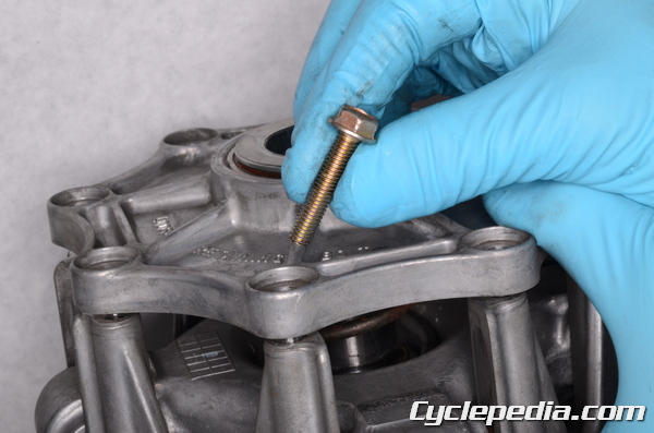
Hold the pulley cover down and remove the eight drive pulley cover bolts.
Allow the cover to be pushed up.
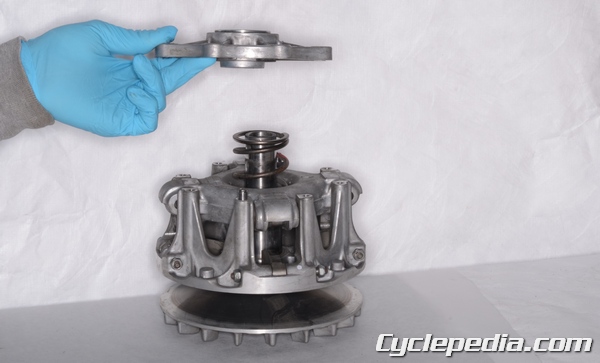
Remove the driven pulley cover.
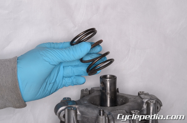
Remove the spring.
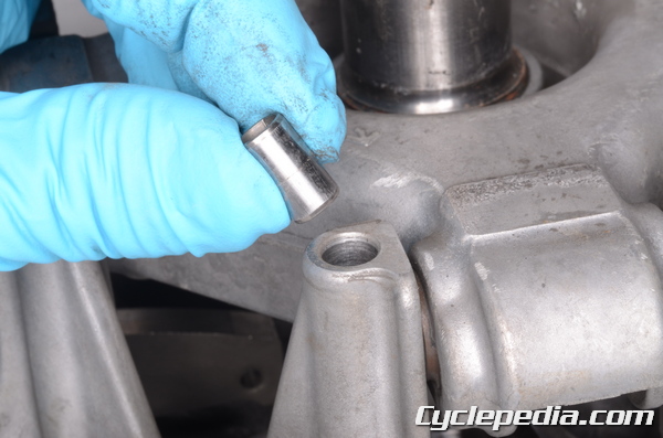
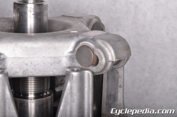
Remove the two pulley cover dowel pins.
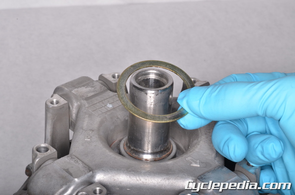
Remove the spacer.
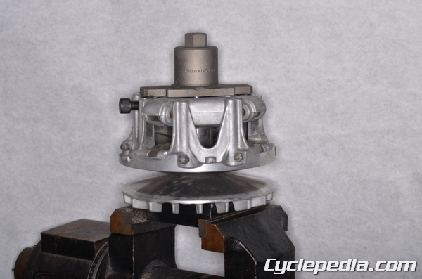
Install the drive pulley wrench onto the spider and tighten its side bolt securely.
Special Tool – Drive Pulley Wrench: 57001-1474
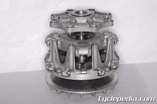
Turn the drive pulley wrench clockwise to remove the spider. Use extreme caution as this is very tight and it will pop when it comes loose.
The spider will raise up out of the movable drive face (sheave).
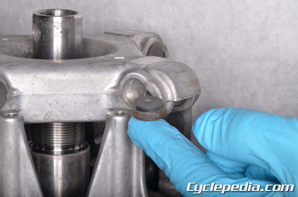
Remove the spider shoes.
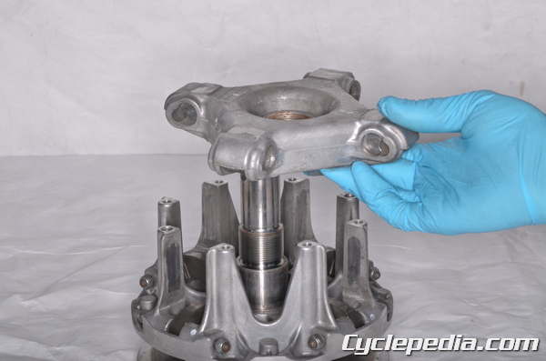
Remove the spider from the movable drive pulley.
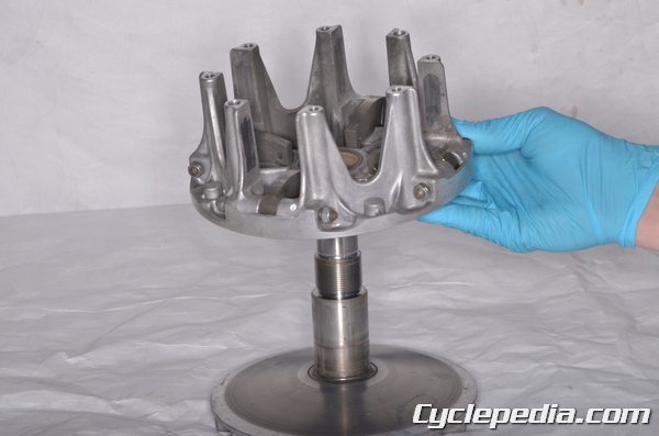
Slide off the movable drive face.
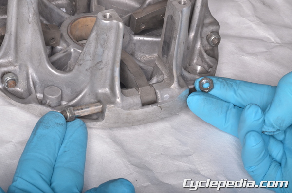
To remove the ramp weights take off the nut with a 10 mm wrench.
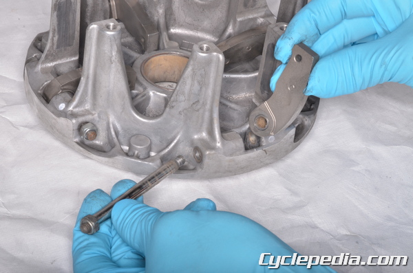
Remove the bolt and ramp weights.
Inspection
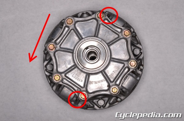
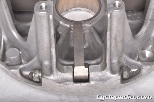
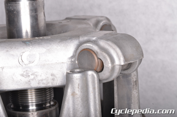
Rotate the movable drive face counterclockwise and check the clearance between the spider shoes and the posts at the indicated locations.
Shoe Side Clearance: 0.15 ~ 0.30 mm (0.0059 ~ 0.012 in.)
If the clearance is out of specification replace the shoes as needed. The optional spacer can also be used if the shoes alone cannot fix the clearance issue (2004 and newer models only).
KVF650-A1, B1 and A2 Early Model
Identification No. of Torque Converter Cover: 72
| Clearance Measurement | Present Shoes | |
| Part Number | Thickness | |
| Less then 0.15 mm (0.0059 in.) (no clearance) | 49048-1078 | 7.2 mm (0.283 in.) |
| 49048-1079 | 7.3 mm (0.287 in.) | |
| 0.15 ~ 0.30 mm (0.0059 – 0.012 in.) (standard clearance) | no change, standard (49048-1080) 7.4 mm (0.291 in.) |
|
| over 0.30 mm (0.012 in.) | 49048-1081 | 7.5 mm (0.295 in.) |
| 49048-1082 | 7.6 mm (0.299 in.) | |
| 49048-1083 | 7.7 mm (0.303 in.) | |
| 49048-1084 | 7.8 mm (0.307 in.) | |
| 49048-1085 | 7.9 mm (0.311 in.) | |
| 49048-1086 | 8.0 mm (0.315 in.) | |
KVF650-A2 Late, B2 Models
Identification No. of Torque Converter Cover: 74
| Clearance Measurement | Present Shoes | |
| Part Number | Thickness | |
| less than 0.15 mm (0.0059 in.) (no clearance) |
49048-1087 | 7.2 mm (0.283 in.) |
| 49048-1088 | 7.3 mm (0.287 in.) | |
| 0.15 ~ 0.30 mm (0.0059 ~ 0.012 in.) (standard clearance) |
no change, standard (49048-1089) 7.4 mm (0.291 in.) |
|
| over 0.30 mm (0.012 in.) | 49048-1090 | 7.5 mm (0.295 in.) |
| 49048-1091 | 7.6 mm (0.299 in.) | |
| 49048-1092 | 7.7 mm (0.303 in.) | |
| 49048-1093 | 7.8 mm (0.307 in.) | |
| 49048-1094 | 7.9 mm (0.311 in.) | |
| 49048-1095 | 8.0 mm (0.315 in.) | |
KVF700-A1/B1 Model
| Part Number | Thickness | |
| Standard Shoe | 49048-1089 | 7.4 mm (0.291 in.) |
| Adjustment Shoes | 49048-1087 | 7.2 mm (0.283 in.) |
| 49048-1088 | 7.3 mm (0.287 in.) | |
| 49048-1090 | 7.5 mm (0.295 in.) | |
| 49048-1091 | 7.6 mm (0.299 in.) | |
| 49048-1092 | 7.7 mm (0.303 in.) | |
| 49048-1093 | 7.8 mm (0.307 in.) | |
| 49048-1094 | 7.9 mm (0.311 in.) | |
| 49048-1095 | 8.0 mm (0.315 in.) |
KVF700-A2/B2/D1 ~ D6F, KVF650 2005 – 2011
| Part Number | Thickness | |
| Standard Shoe | 49048-1090 | 7.5 mm (0.295 in.) |
| Adjustment Shoes | 49048-1087 | 7.2 mm (0.283 in.) |
| 49048-1088 | 7.3 mm (0.287 in.) | |
| 49048-1089 | 7.4 mm (0.291 in.) | |
| 49048-1091 | 7.6 mm (0.299 in.) | |
| 49048-1092 | 1J mm (0.303 in.) | |
| 49048-1093 | 7.8 mm (0.307 in.) | |
| 49048-1094 | 7.9 mm (0.311 in.) | |
| 49048-1095 | 8.0 mm (0.315 in.) |
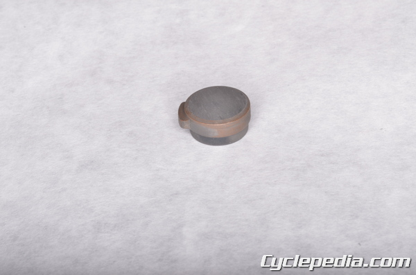
Check the spider shoes for excessive wear and damage.
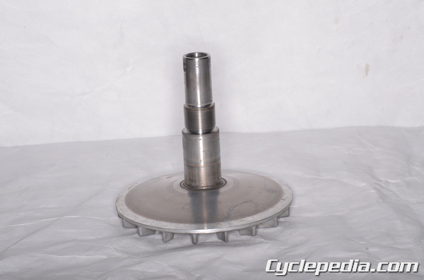
Inspect the dive pulley faces for damage, wear, and grease contamination. Clean the faces and replace them if they are damaged.
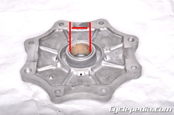
Inspect the cover bushing for damage and wear. Measure its inside diameter with vernier calipers.
Cover Bushing I.D.: 27.985 ~ 28.085 mm (1.1018 ~ 1.1057 in.)
Service Limit: 28.12 mm (1.107 in.)
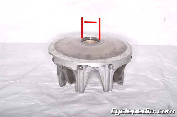
Inspect the movable drive face (sheave) bushing for damage and wear. Measure its inside diameter with vernier calipers.
| Item | Standard | Service Limit |
| Sheave bushing I.D. | 37.985 ~ 38.085 mm (1.4955 ~ 1.4994 in.) | 38.12 mm (1.501 in.) |
Sheave Bushing I.D.: 37.985 ~ 38.085 mm (1.4955 ~ 1.4994 in.)
Service Limit: 38.12 mm (1.501 in.)
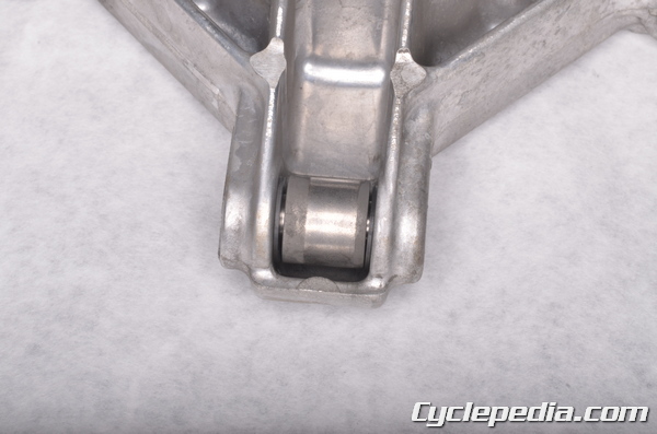
Inspect the ramp weights and rollers for wear and damage. Replace the parts as needed. If the rollers need to be replace the spider must be replaced as a whole.
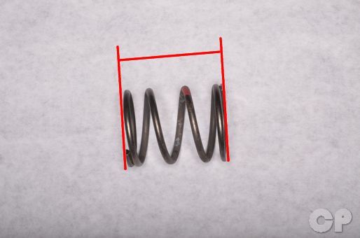
Inspect the spring ford damage and fatigue. Measure the free length of the spring and replace it as needed.
Spring Free Length
2002 – 2003: 62 mm (2.44 in.)
2005 – 2011 and 700: 60.4 mm (2.44 in.)
Assembly
Install the ramp weights onto the movable drive face. Tighten the nuts to specification with a 10 mm wrench. The ramps must move smoothly.
Ramp Weight Nuts: 6.9 N-m, 0.7 kgf-m, 61 in-lb
Make sure the treads of the fixed drive face and spider are clean. clean the drive faces with an oil free cleaning solvent.
Thread the 57001-1412 into 57001-1473. Secure the holder tools in a vise so the holder plate protrudes 7 mm above the vise jaws.
Special Tools
Drive and Driven Pulley Holder: 57001-1473
Drive and Driven Pulley Holder: 57001-1412
Place the fixed drive face onto the special tools. Fit the movable drive face onto the fixed drive face. Make sure the movable drive face moves smoothly on the fixed drive face.
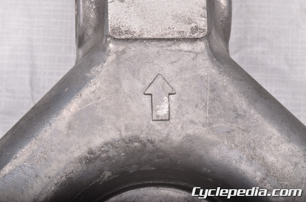
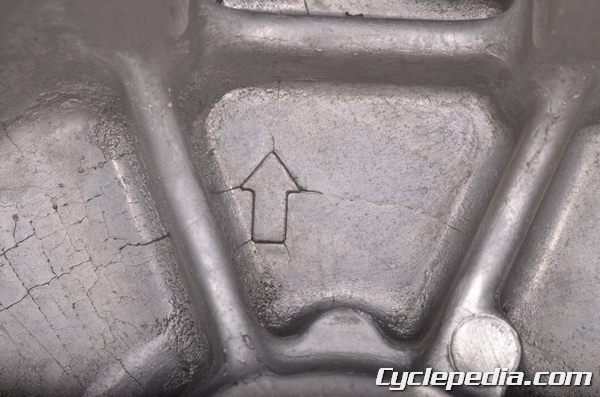
When installing the spider into the movable drive face make sure the arrows line up.
Install the spider onto the movable drive face.
Install the spider shoes so the rubber side is on the inside. Make sure the spider shoes stay in place as the spider is fit into the movable drive face.
Install the drive pulley wrench onto the spider and tighten its side bolt securely.
Special Tool – Drive Pulley Wrench: 57001-1474
Turn the drive pulley wrench counterclockwise to join the spider to the fixed drive face. Toque the spider to specification and then remove the special wrench.
Spider: 275 N-m, 28 kgf-m, 203 ft-lb
Install the space.
Install the spring.
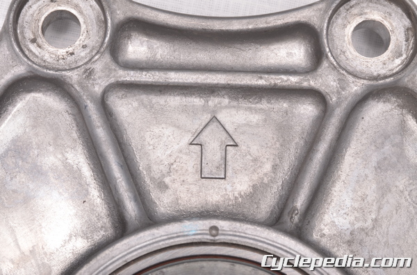
When installing the cover onto the spider make sure the arrows line up.
Install the two pulley cover dowel pins.
Install the pulley cover.
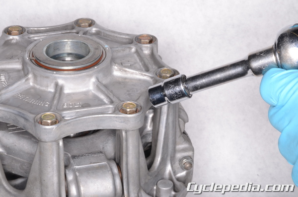
Hold the cover down against the spring and thread in the eight bolts. Tighten the cover bolts in a crisscross pattern. Toque the cover bolts to specification with a 10 mm socket.
Drive Pulley Cover Bolts: 13 N-m, 1.3 kgf-m, 113 in-lb
Installation
To install the drive pulley and belt see the Drive Belt topic.