
 Like this Manual?
SAFETY FIRST: Protective gloves and eyewear are recommended at this point.
Removal
Remove the cylinder head covers. See the Cylinder Head Covers topic.
Remove the camshafts. See the Camshafts topic.
Remove the alternator flywheel and starter clutch gear. See the Alternator topic.
Remove the oil pump. See the Oil Pump topic.
Remove the CVT cover. See the CVT Cover topic.
Remove the drive belt and drive pulley. See the Drive Belt topic.
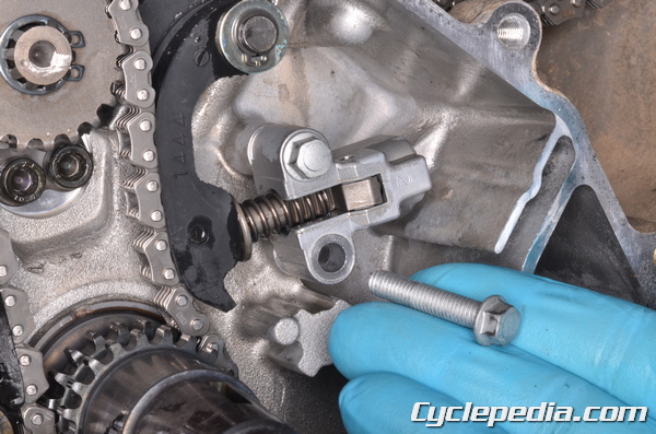
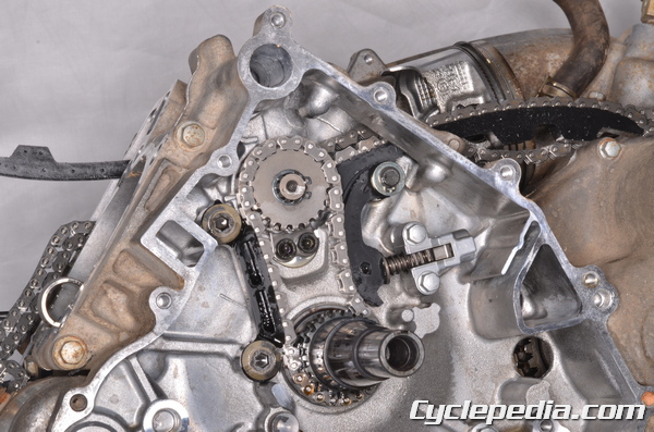
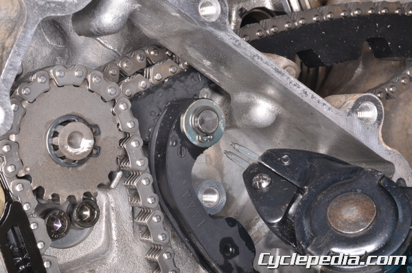
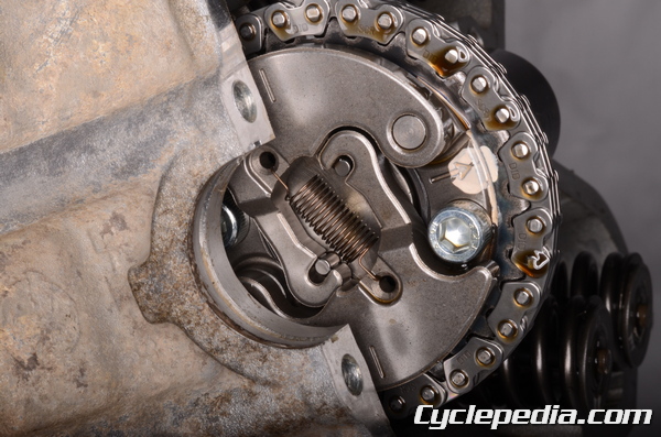
Remove the two intermediate cam chain tensioner mounting bolts with an 8 mm socket.
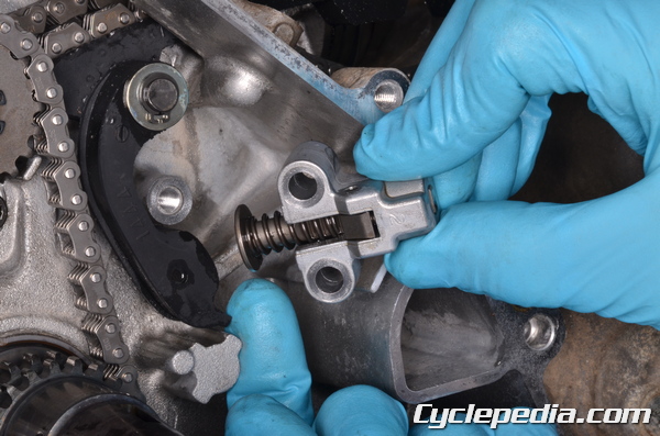
Remove the intermediate cam chain tensioner.
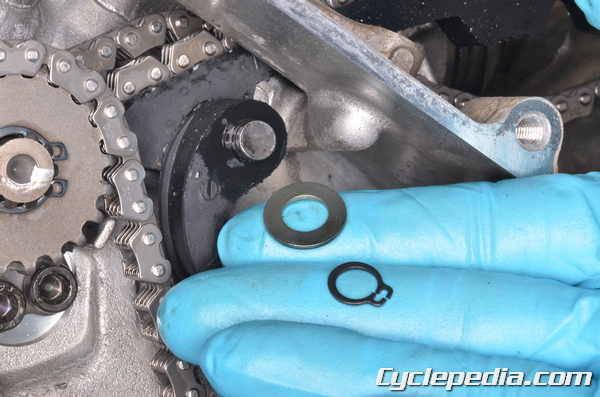
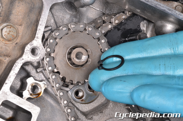
Remove the snap ring and washer. Use snap ring pliers to spread the snap ring.
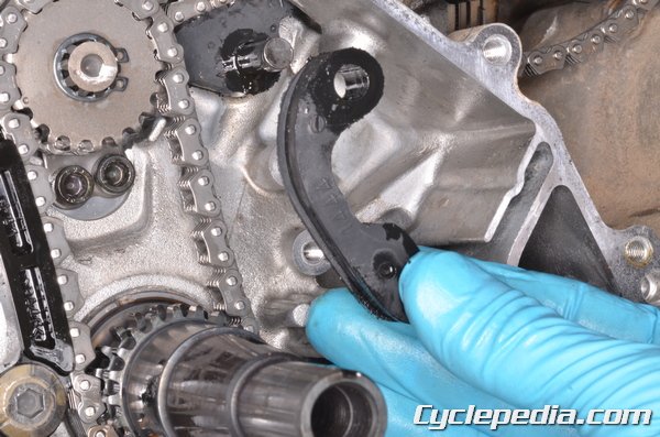
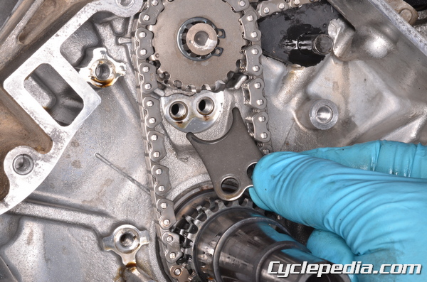
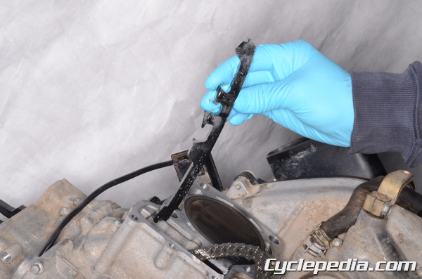
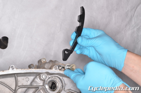
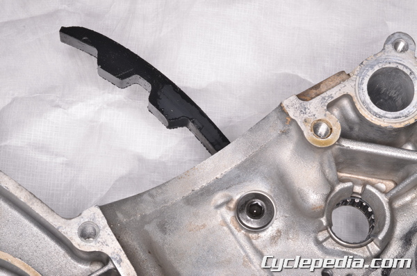
Remove the rear intermediate cam chain guide.
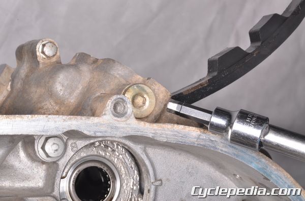
Remove the front intermediate cam chain guide bolts with a 6 mm Allen.
Remove the intermediate cam chain guide.
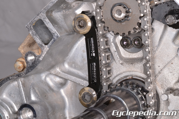
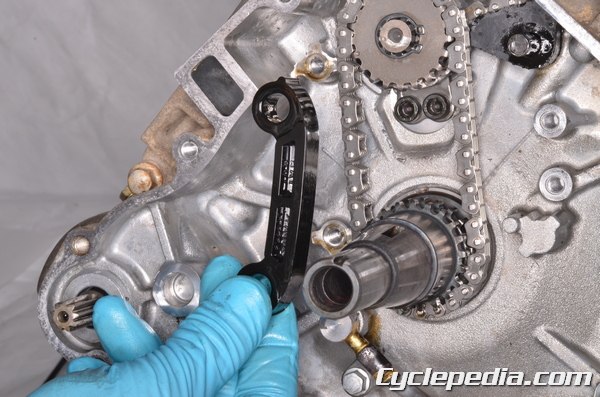
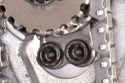
Remove the two position plate bolts with a 5 mm Allen.
Remove the position plate.
Remove the intermediate timing shaft snap ring on the 2005 and newer models. On the 2002 – 2004 models remove the intermediate timing shaft nut.
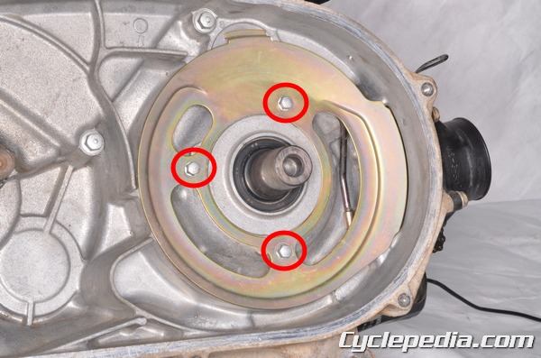
Remove the three drive pulley plate bolts with an 8 mm socket.
Remove the drive pulley plate.
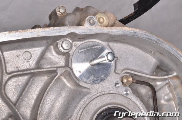
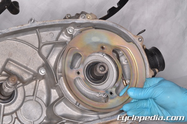
Thread an M6 bolt into the intermediate shaft cover.
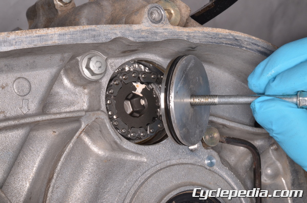
Remove the intermediate shaft cover. Discard the O-ring.
Free the front cylinder cam chain from the intermediate timing shaft.
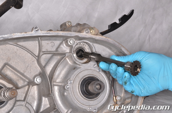
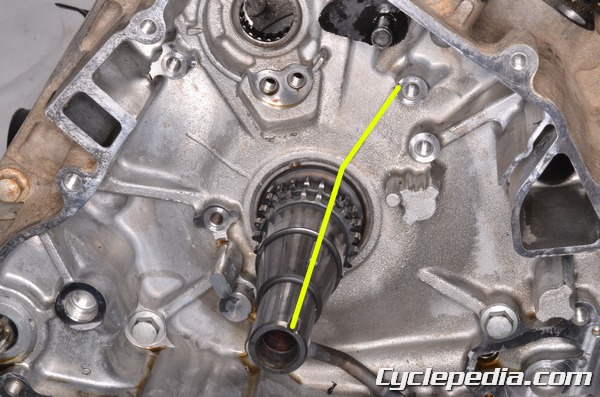
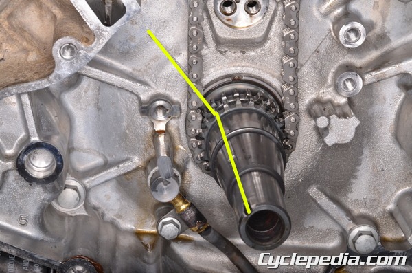
Remove the intermediate timing shaft from the right side of the crankcase.
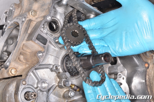
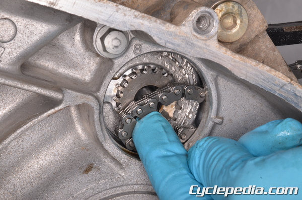
Remove the intermediate sprocket and intermediate cam chain.
Free the rear cam chain from the intermediate sprocket.
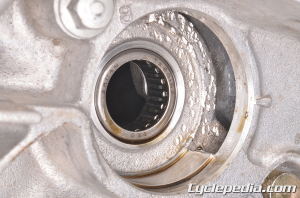
Inspect the intermediate shaft bearings by turning them with a finger. Replace these bearings as needed. See the Crankcase Bearings topic for more information.
Installation
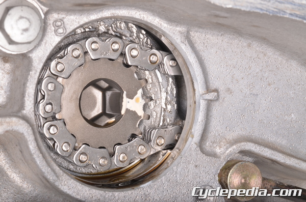
Position the crankshaft so the flywheel key groove lines up with the index mark on the crankcase.
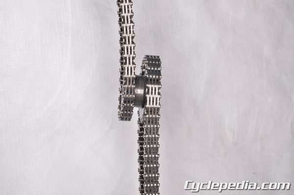
Engage the rear cam chain and intermediate cam chain to the intermediate sprocket. Fit the intermediate sprocket into place with the intermediate chain on the left side.
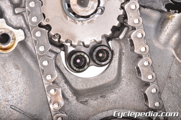
Insert the intermediate shaft into the right side of the crankcase and into the sprocket. The intermediate shaft must fit into the sprocket so that the wide sprocket tooth fits into the wide gap on the shaft (see below). Also the punch mark on the intermediate shaft mush line up with the punch mark on the sprocket.

Fit the rear cam chain around its cam sprocket. The arrow on the camshaft sprocket must be facing up, and the lines on the weights should be level with the cylinder head-to-cylinder head cover mating surface.
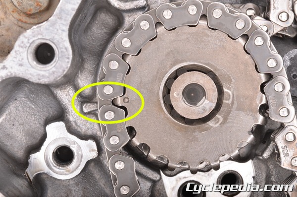
While maintaining the position of the crank described above. The punch mark on the intermediate sprocket must line up with the projection on the crankcase. Note: the punch mark on the shaft also lines up with the sprocket.
Install a new snap ring into the groove on the intermediate timing shaft on the 2005 – 2011 models. On the 2002 – 2004 models install the intermediate shaft nut and tighten it to specification.
Intermediate Shaft Sprocket Nut [2002 – 2004]: 44 N-m, 4.5 kgf-m, 33 ft-lb
Rotate the crankshaft 270° clockwise so that the flywheel key groove lines up with the index mark on the crankcase.
Fit the front cylinder cam chain onto the intermediate timing shaft. Note the alignment marks.
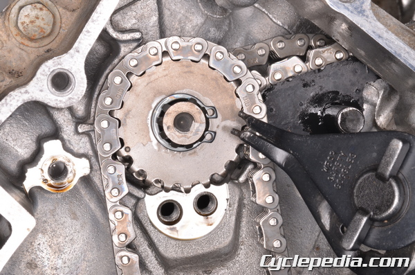
Move the intermediate shaft all the way to the left. Install the position plate so that it sits to the right of the rear cam chain.
Install the two position plate bolts and tighten them to specification with a 5 mm Allen.
Position Plate Bolts: 8.8 N-m, 0.9 kgf-m, 78 in-lb
Install a new O-ring onto the intermediate shaft cover. Apply a light coat of grease to the O-ring. Fit the intermediate shaft cover into place so that the threaded hole side faces out. Wipe away any excess grease.
Fit the drive pulley plate into place and thread in the three bolts. Tighten the three drive pulley plate bolts securely with an 8 mm socket.
Set the front intermediate cam chain guide into place and thread in its two mounting bolts. Tighten the front intermediate cam chain guide bolts to specification with a 6 mm Allen.
Intermediate Shaft Sprocket Nut [2002 – 2004]: 44 N-m, 4.5 kgf-m, 33 ft-lb
Intermediate Shaft Chain Guide Bolts [2005 – 2011]: 8.8 N-m, 0.9 kgf-m, 78 in-lb
Install the rear intermediate cam chain guide.
Install the washer and a new snap ring. Use snap ring pliers to spread the snap ring and fit it into its groove.
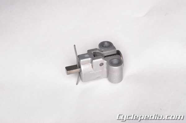
Retract the intermediate cam chain tensioner rod all the way and secure it with a length of wire.
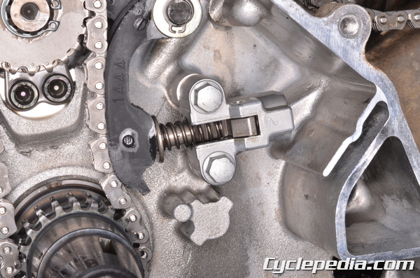
Install the intermediate cam chain tensioner. Tighten the two bolts to specification with an 8 mm socket. Remove the wire and allow the tensioner rod to extend.
Intermediate Shaft Chain Tensioner Bolts: 8.8 N-m, 0.9 kgf-m, 78 in-lb
Verify the alignment marks of the punch mark on the intermediate shaft and arrow on the crankcase.
Install the front camshaft. See the Camshafts topic for more information.
Install the drive belt and drive pulley. See the Drive Belt topic.
Install the CVT cover. See the CVT Cover topic.
Install the oil pump. See the Oil Pump topic.
Install the alternator. See the Alternator topic.
Install cylinder head covers. See the Cylinder Head Covers topic.
Double check the engine timing and check the valve clearance. See the Valve Adjustment topic.
Cam Chain Guides
Remove the cylinder head to access the front cam chain guides for each cylinder. See the Cylinder Heads topic for more information.
Remove the cylinders to access the rear cam chain guides for each cylinder. See the Cylinders topic for more information.
To remove the rear cam chain guides for each cylinder take out the bolt with a 6 mm Allen socket.
The bolt for the front cylinder is on the outside of the crankcase.
The bolt for the rear cylinder is inside the crankcase and can be accessed from the cylinder opening.
Tighten the cam rear cam chain guide bolts to specification on installation.
Cylinder Camshaft Chain Guide Bolt: 20 N-m, 2.0 kgf-m, 14 ft-lb
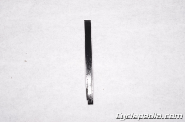
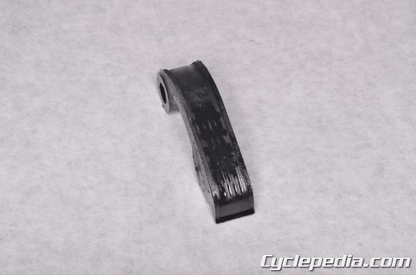
Inspect the cam chain guides for excessive wear and damage.