
 Like this Manual?
SAFETY FIRST: Protective gloves and eyewear are recommended at this point.
Removal
Bevel Gear Cover
Drain the engine oil. See the Engine Oil topic for more information.
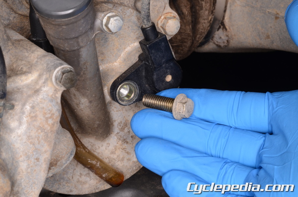
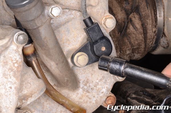
Remove the forward/reverse detecting sensor mounting bolt with an 8 mm socket.
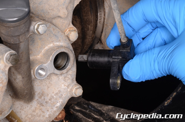
Remove the forward/reverse detecting sensor.
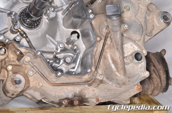
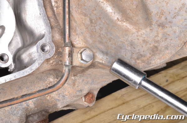
Remove the three outer oil pipe bolts with an 8 mm socket.
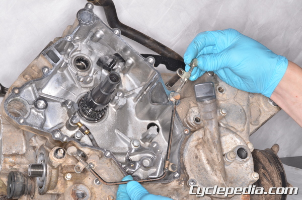
Remove the outer oil pipe.
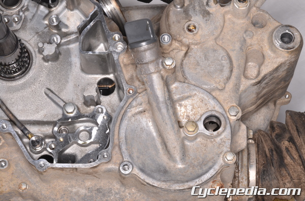
The bevel gear cover is held on by three bolts, one of which was removed with the outer oil pipe.
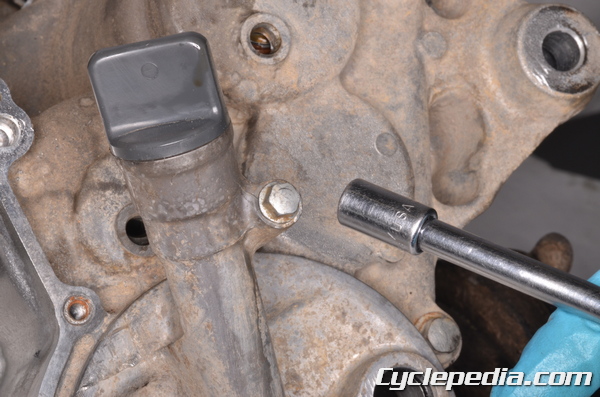
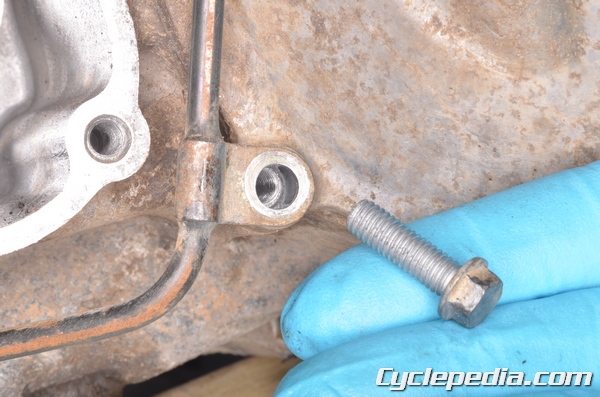
Remove the two remaining bevel gear cover bolts with an 8 mm socket.
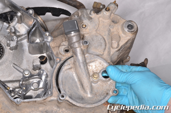
Remove the bevel gear cover.
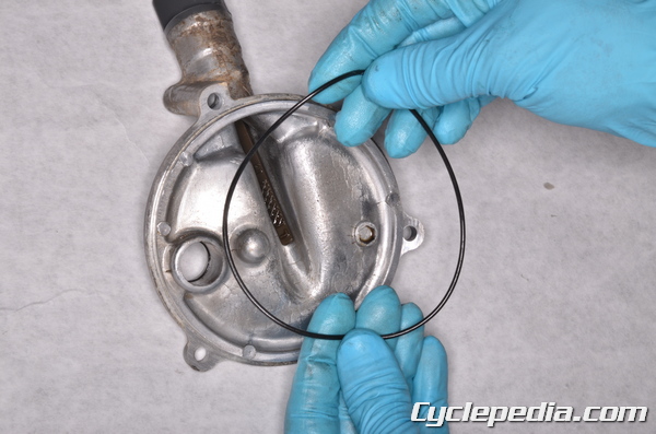
Inspect the bevel gear cover O-ring and replace it as needed. Do the same with the forward/reverse detecting sensor O-ring.
Output Drive Idle Gear
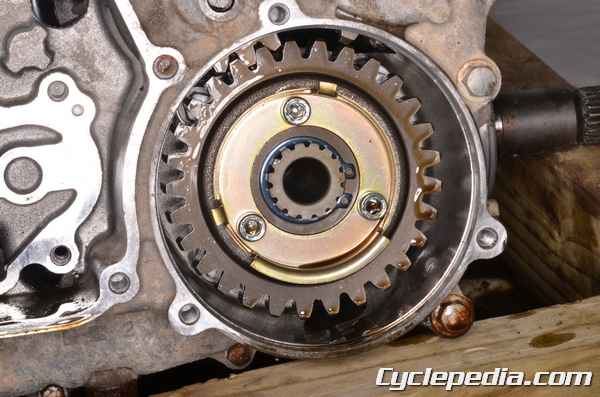
If the forward/reverse detecting sensor rotor needs to be removed go ahead and loosen the three rotor bolts with a 5 mm Allen while it is installed.
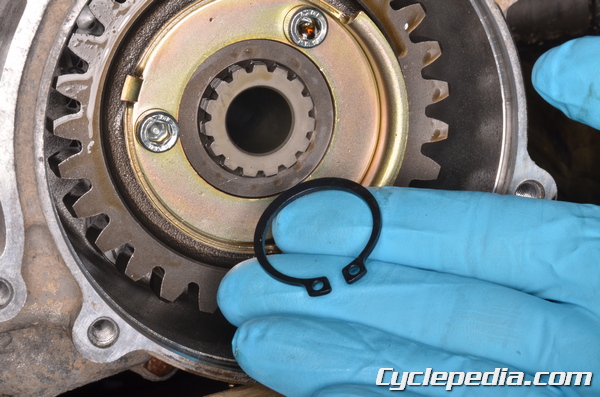
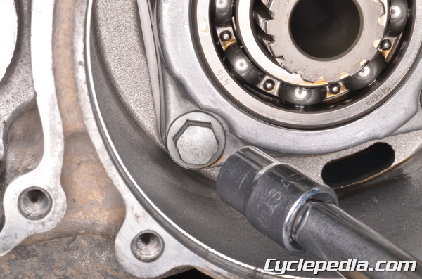
Remove the output drive idle gear snap ring with snap ring pliers.
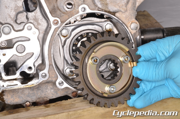
Remove the output drive idle gear.
Output Drive Bevel Gear Housing
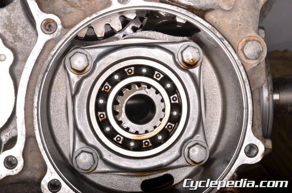
The output bevel gear housing is held to the crankcase by four bolts.
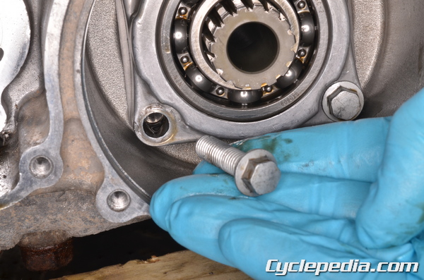
Remove the output bevel gear housing bolts with an 8 mm socket.
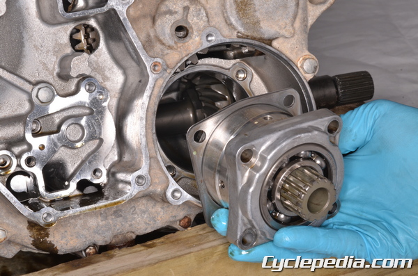
Remove the output bevel gear housing and shim/s from the left crankcase.
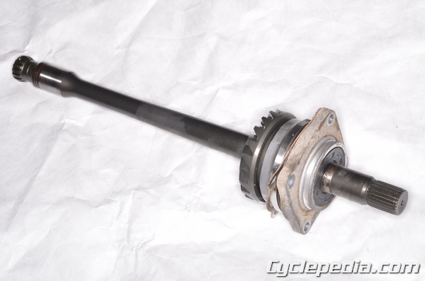
Output Driven Bevel Gear
The output driven bevel gear and shaft are inside the engine cases. The crankcases do not need to be split to remove these components.
Remove the swingarm. See the Swingarm topic for more information.
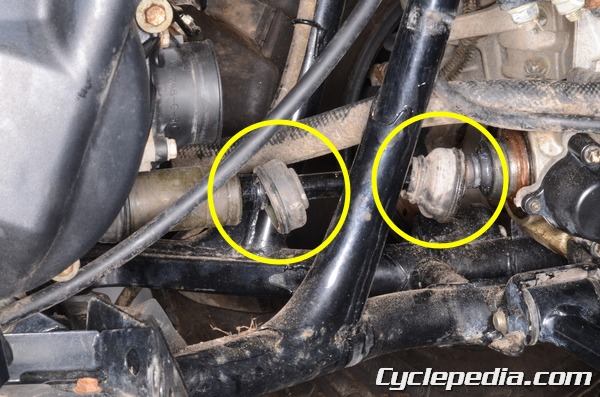
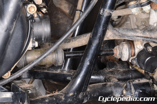
Slide back the O-ring clamps from the rubber covers of the front propeller shaft. Slide back the rubber front propeller shaft covers.
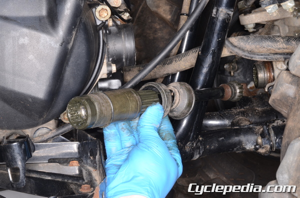
Move the front propeller shaft back towards the engine and free the front end of the shaft from the front differential. Move the shaft forward and free the rear of the shaft from the engine. Remove the front propeller shaft.
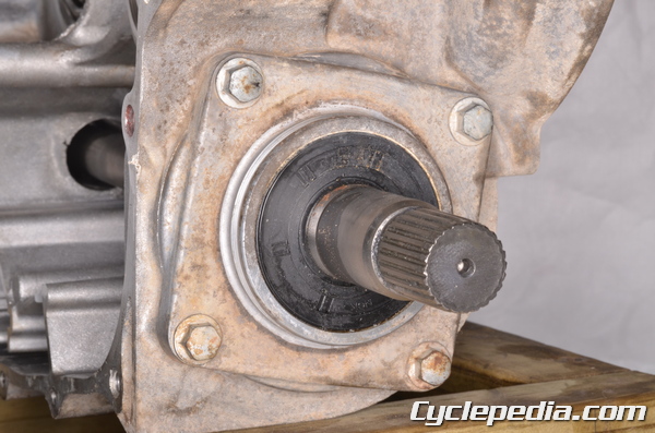
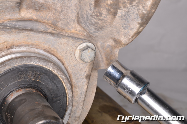
The output driven bevel gear housing is held to the back of the right crankcase with four mounting bolts.
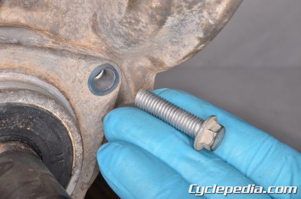
Remove the output driven bevel gear housing bolts with an 8 mm socket.
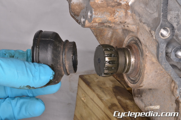
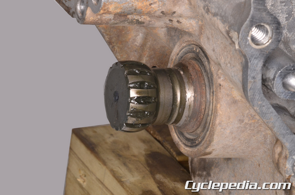
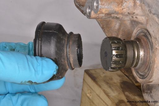
Remove the rubber boot from the front of the output driven bevel gear shaft.
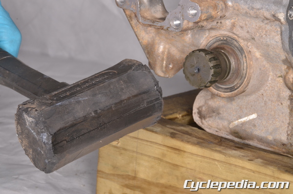
Tap on the front of the output driven bevel gear shaft with a rubber mallet.
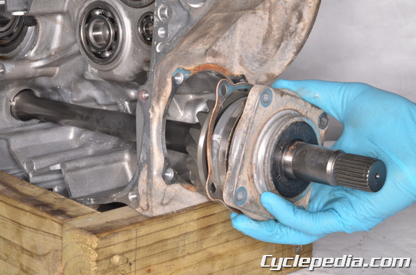
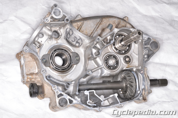
Remove the output driven bevel gear housing and gasket.
Inspection
Inspect the bevel gear components. Check for gear backlash and tooth contact pattern. See the Bevel Gear Inspection topic for more information.
Installation
Install the correct shims with the drive and driven bevel gear housings for correct gear backlash and tooth contact. See the Bevel Gear Inspection topic for more information.
Output Driven Bevel Gear
Make sure the housing mating surface is clean.
Install the shim/s and a new O-ring to the output driven bevel gear housing. Coat the new O-ring in grease.
The shaft will pass through an oil seal at the front of the crankcase. Make sure this oil seal is in good condition. Coat the lips of the oil seal in grease.
Fit the output driven bevel gear shim/s and housing into place. Guide the shaft carefully through the crankcase.
Install the four output driven bevel gear housing bolts and tighten them to specification with an 8 mm socket.
Output Driven Bevel Gear Housing Bolts: 26 N-m, 2.7 kgf-m, 20 ft-lb
Clean off the old grease from the front propeller shaft splines. Inspect the splines for wear and damage and replace the parts as needed. Lubricate the splines with fresh molybdenum disulfide grease.
Place the rubber boot on the front of the output driven bevel gear shaft if it was removed. When installing the rubber boots the O-ring clamps must land in the grooves on the shaft to be secure.
Install the propeller shaft to the engine and pull it back. Fit the front of the shaft into the front differential.
Slide the rubber covers into place. Secure the rubber covers with the O-ring clamps.
Install the swingarm. See the Swingarm topic for more information.
Output Drive Bevel Gear Housing
Install the output bevel gear housing and shim/s into the left crankcase.
Install the four output bevel gear housing bolts and tighten them to specification with an 8 mm socket.
Output Drive Bevel Gear Housing Bolts: 26 N-m, 2.7 kgf-m, 20 ft-lb
Output Drive Idle Gear
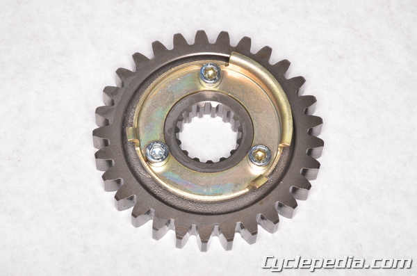
Install the forward/reverse detecting sensor rotor with its projections facing out. Tighten the three bolts to specification with a 5 mm Allen.
Rotor Mounting Bolts: 12 N-m, 1.2 kgf-m, 104 in-lb

Fit the output idle gear into place. Install a new snap ring into the groove.
Bevel Gear Cover
Install good O-rings on the bevel gear cover and coat the O-rings in fresh engine oil.
Install the bevel gear cover. Install the two rear bevel gear cover bolts and tighten them to specification with an 8 mm socket.
Output Drive Bevel Gear Cover Bolts: 8.8 N-m, 0.9 kgf-m, 78 in-lb
Lubricate the oil pip O-rings with fresh engine oil. Fit the outer left side oil pipe into place.
Insert the three outer oil pipe bolts and tighten them to specification with an 8 mm socket.
Oil Pipe Bolts: 8.8 N-m, 0.9 kgf-m, 78 in-lb
Install the forward/reverse detecting sensor and tighten the mounting bolt to specification with an 8 mm socket.
Forward/Reverse Detecting Sensor Bolt: 15 N-m, 1.5 kgf-m, 11 ft-lb
Fill the engine oil. See the Engine Oil topic for more information.