
 Like this Manual?
SAFETY FIRST: Protective gloves and eyewear are recommended at this point.
Engine Braking Actuator
Removal
Be sure that the ignition is in the OFF position.
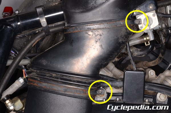
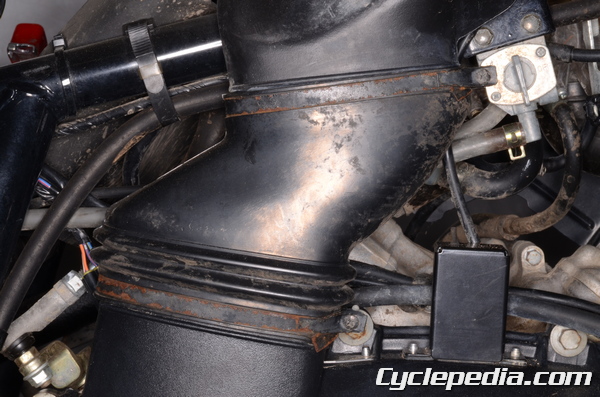
Loosen the air duct clamp screws with a #2 Phillips screwdriver.
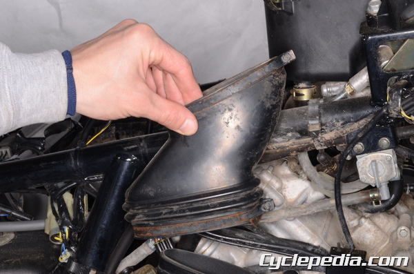
Remove the air duct.
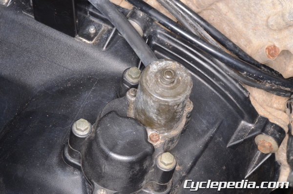
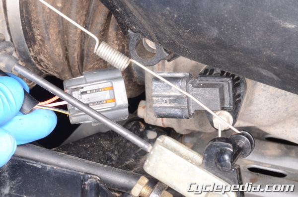
The engine braking actuator is located on top of the torque converter cover. Trace the wires up from the engine braking actuator.
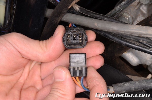
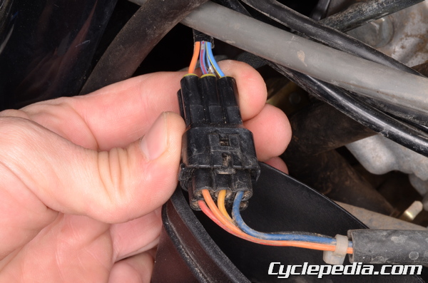
Unplug the engine braking actuator connector.
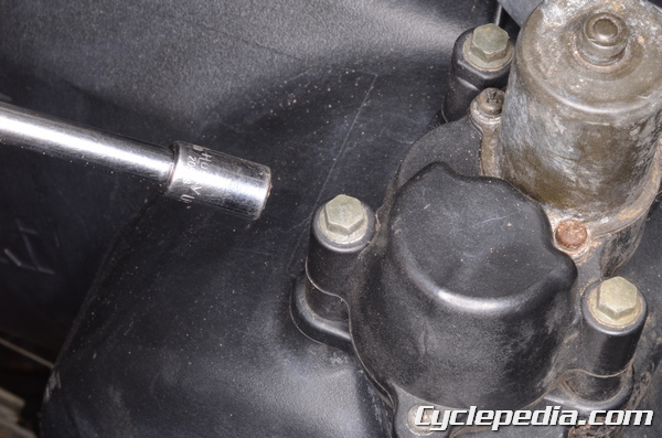
Remove the three engine braking actuator mounting bolts with an 8 mm socket.

Remove the engine braking actuator from the torque converter cover.
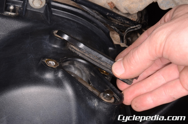
Remove the trim cover and seal. Inspect the seal for damage and wear and replace it as needed.
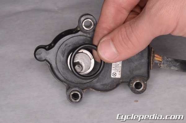
Remove the O-ring from the engine braking actuator. Replace it if it is in poor condition.
Installation
Apply molybdenum disulfide grease to the O-ring and actuator pin. Install the O-ring onto the actuator.
Apply grease to the trim cover seal and install the trim cover into the torque converter cover.
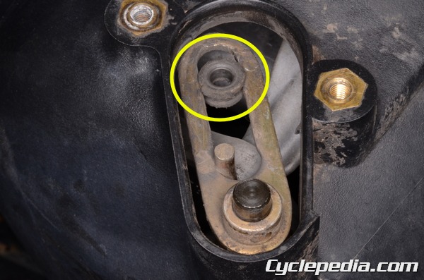
When the actuator is installed the pin must fit into the collar in the engine brake lever assembly.
Install the actuator into the torque converter cover. Install the three mounting bolts and tighten them evenly and in a crisscross pattern. Torque the bolts to specification with an 8 mm socket.
Engine Brake Actuator Mounting Bolts: 8.8 N-m, 0.9 kgf-m, 78 in-lb
Plug in the engine braking actuator connector.
Install the air duct.


Tighten the air duct clamp screws securely with a #2 Phillips screwdriver.
2WD / 4WD Actuator
Removal
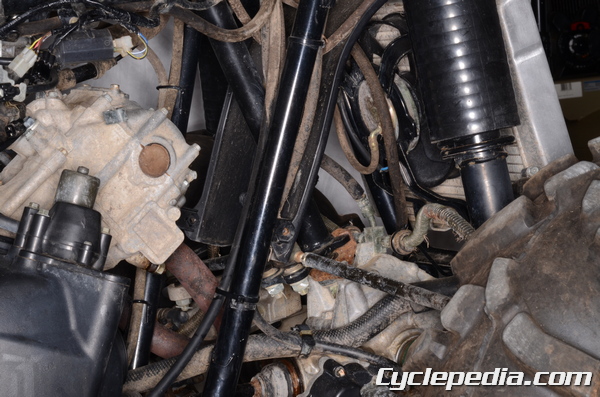
Remove the right side rear inner cover. See the Inner Covers topic for more information.
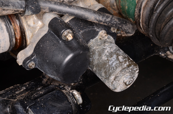
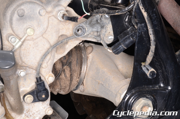
the 2WD / 4WD actuator is located on the right side of the front differential.
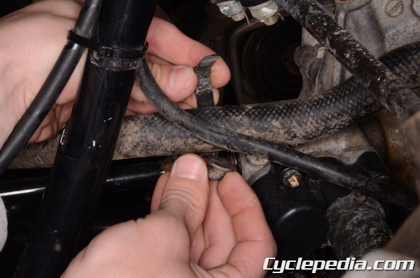
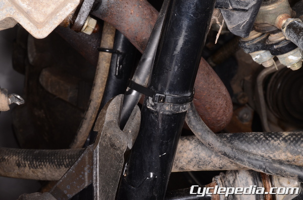
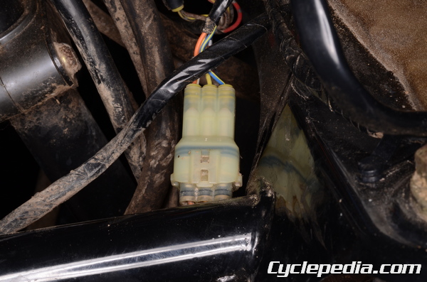
Free the 2WD / 4WD actuator wires from the two wire bands.
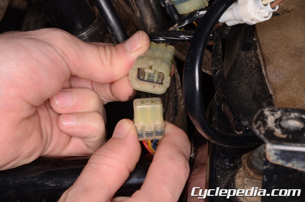
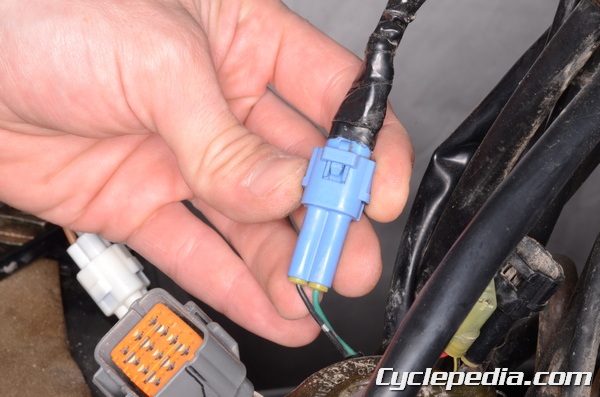
Unplug the 2WD / 4WD actuator connector.
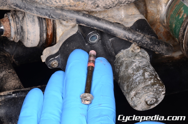
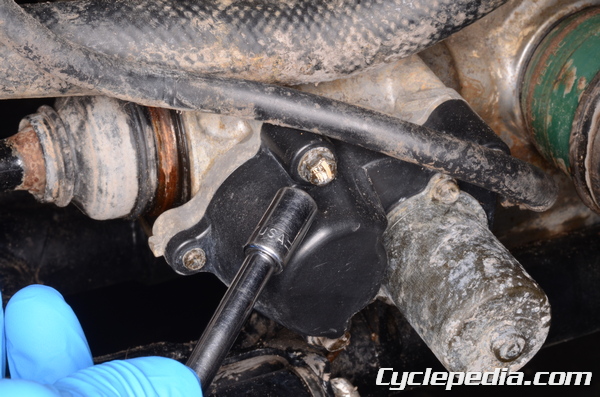
Remove the three 2WD / 4WD actuator mounting bolts with an 8 mm socket.
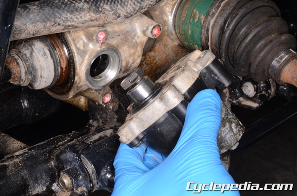
Remove the 2WD / 4WD actuator from the front differential.
Remove the O-ring from the 2WD / 4WD actuator. Replace it if it is in poor condition.
Installation
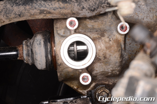
When the 2WD / 4WD actuator is installed its collar must fit into the groove on the 2WD / 4WD shifter.
Apply molybdenum disulfide grease to the O-ring and actuator collar. Install the O-ring onto the actuator. Install the 2WD / 4WD actuator into the right side of the front differential. Install the three 2WD / 4WD actuator mounting bolts and tighten them evenly and in a crisscross pattern. Torque the bolts to specification with an 8 mm socket.
2WD/4WD Actuator Mounting Bolts
2002 – 2003, 700cc: 9.8 N-m, 1.0 kgf-m, 87 in-lb
2005 – 2011: 8.8 N-m, 0.9 kgf-m, 78 in-lb
Plug in the 2WD / 4WD actuator connector.
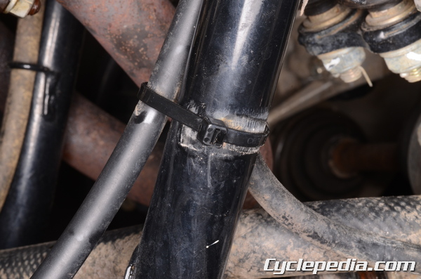
Secure the 2WD / 4WD actuator wires with the two wire bands.
Install the right side rear inner cover. See the Inner Covers topic for more information.
Inspection
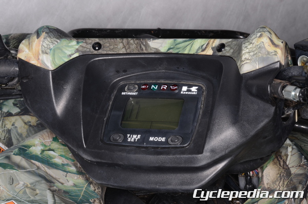
When there is a problem with an actuator the 2WD and 4WD indicators will flash in an alternating pattern.
2002 – 2008 Models
Failure Indicator Pattern | Failed Component
0.5 sec 2WD alternating with 0.5 sec 4WD | 2WD/4WD Actuator
1.0 sec 2WD alternating with 1.0 sec 4WD | Engine Brake Actuator
2.0 sec 2WD alternating with 2.0 sec 4WD } Both Actuators
2009 and Newer Models
Failure Indicator Pattern | Failed Component
0.5 sec 2WD alternating with 3.0 sec 4WD | 2WD/4WD Actuator
3.0 sec 2WD alternating with 0.5 sec 4WD | Engine Brake Actuator
3.0 sec 2WD alternating with 3.0 sec 4WD | Both Actuators
Troubleshooting
Failed Component: 2WD/4WD Actuator
Probable Causes
2WD/4WD Actuator
Controller Power Supply
Speed Sensor
2WD/4WD Switch
Controller
Failed Component: Engine Brake Actuator
Probable Causes
Engine Brake Actuator
Controller Power Supply
Speed Sensor
Forward/Reverse Sensor
Controller
Failed Component: 2WD / 4WD Lights Don’t Switch
Probable Cause: Both Actuators
To troubleshoot the actuators, you will need a digital multimeter. Before performing any tests make sure the electrical connections are not loose or corroded. Do not disconnect electrical connectors with the ignition switch in the ON position.
Special Tool – Hand Tester: 57001-1394
2WD / 4WD Actuator Inspection
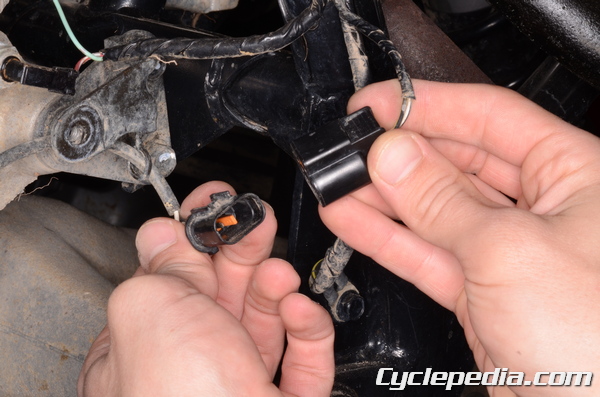
Unplug the 2WD / 4WD actuator connector.
Set the multimeter to read ohms of resistance (Ω – kΩ).
Check the resistance between the wire terminals of the actuator side connector as indicated. Replace the actuator if the resistance is out of specification.
Terminal Wire Colors | Resistance
red – black | 3 – 15 Ω
orange – blue | 3.5 – 6.5 kΩ
yellow – blue | 630 – 5,330
Engine Braking Actuator Inspection
Unplug the engine braking actuator connector.
Set the multimeter to read ohms of resistance (Ω – kΩ).
Check the resistance between the wire terminals of the actuator side connector as indicated. Replace the actuator if the resistance is out of specification.
Terminal Wire Colors | Resistance
red – black | 3 – 15 Ω
orange – blue | 3.5 – 6.5 kΩ
yellow – blue | 630 – 5,330
Controller Power Supply Inspection
Turn the ignition switch to the OFF position.
Make sure the battery has a full charge.
Remove the seat. See the Seat topic for more information.
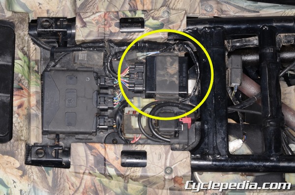
Locate the controller unit.
Set the multimeter to read voltage (25 VDC).
Use the needle adapter set to test the voltage in the controller connector while it is plugged in.
Special Tools – Needle Adapter Set: 57001-1394

Touch the positive meter lead to the brown wire and the negative meter lead to the black/yellow wire. Turn the ignition switch to the ON position and check the voltage.
The multimeter should read battery voltage.
If the battery voltage doesn’t show check the 30A fuse, ignition switch, and wiring harness.
Speed Sensor Inspection
Test the speed sensor as with the controller power supply inspection.
Touch the positive meter lead to the pink wire and the negative meter lead to the black/yellow wire. Turn the ignition switch to the ON position and turn the rear wheel.
The multimeter should show 0 – 5 volts.
If the reading is out of specification replace the speed sensor.
2WD / 4WD Shift Switch

Test the 2WD / 4WD shift switch as with the controller power supply inspection.
Touch the positive meter lead to the green wire and the negative meter lead to the black/yellow wire. Turn the ignition switch to the ON position and the 2WD / 4WD shift switch to 4WD.
The multimeter should show ~ 5 volts.
If the reading is out of specification check the switch and the actuator. See the Switches topic for more information on the switch testing.
Turn the 2WD / 4WD shift switch to 2WD.
The multimeter should show 0 volts.
If the reading is out of specification check the controller unit and the actuator.
Controller Unit
Replace the controller unit if any of the output voltage measurements are out of specification.
Turn the ignition switch to the OFF position.
Make sure the battery has a full charge.
Remove the seat. See the Seat topic for more information.
Locate the controller unit.
Use the needle adapter set to test the output voltage in the controller connector while it is plugged in.
Special Tools – Needle Adapter Set: 57001-1394
Actuator Controller Output Voltage
Set the multimeter to read voltage (10 VDC).
Touch the positive meter lead to the orange wire and the negative meter lead to the black/yellow wire. Turn the ignition switch to the ON position.
The multimeter should show 4.8 ± 0.2 volts.
Speed Sensor Controller Output Voltage
The speed sensor is located on the right side of the engine below the torque converter cover.
Unplug the speed sensor connector.
Set the multimeter to read voltage (10 VDC).
Touch the positive meter lead to the pink wire and the negative meter lead to the black/yellow wire. Turn the ignition switch to the ON position.
The multimeter should show 5 ± 0.25 volts.
2WD / 4WD Shift Switch Controller Output Voltage
Remove the front fender and locate the 2WD / 4WD shift switch connector. See the Front Fender topic for more information.
Set the multimeter to read voltage (10 VDC).
Touch the positive meter lead to the green wire and the negative meter lead to the black/yellow wire. Turn the ignition switch to the ON position.
The multimeter should show 5 ± 0.25 volts.
Engine Brake Actuator Controller Output Voltage
Support the vehicle with a suitable stand or jack so that the wheels are not touching the ground.
Set the multimeter to read voltage (25 VDC).
Touch the positive meter lead to the white/red wire and the negative meter lead to the black/yellow wire. Turn the ignition switch to the ON position and turn a rear wheel as if in forward motion. Turn the ignition switch to the OFF position one second after the rear wheel stops turning. Wait two seconds and measure the controller output voltage to the engine brake actuator until the engine brake actuator ends its function.
The multimeter should show 5 ~ 12 volts.
If the reading is out of specification there is a problem with either the controller unit or the forward/reverse detecting sensor.
2WD / 4WD Actuator Controller Output Voltage
Set the multimeter to read voltage (25 VDC).
Touch the positive meter lead to the white/yellow wire and the negative meter lead to the black/yellow wire. Turn the ignition switch to the ON position and the 2WD / 4WD switch to the 2WD position. Turn the ignition switch to the OFF position one second after the rear wheel stops turning. Wait two seconds and measure the controller output voltage to the engine brake actuator until the engine brake actuator ends its function.
The multimeter should show 5 ~ 12 volts.
If the reading is out of specification there is a problem with either the controller unit or the 2WD / 4WD switch.
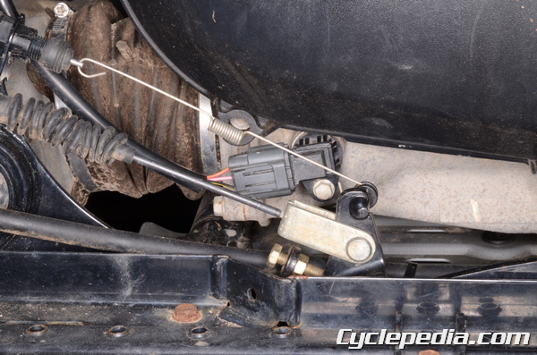
Forward / Reverse Sensor Inspection
Remove the rear fender. See the Rear Fender topic.
The forward / reverse detecting sensor is located to the rear of the engine oil dip stick.
Unplug the forward / reverse detecting sensor connector.
Set the multimeter to read ohms of resistance (kΩ).
Measure the resistance between the wire terminals of the forward / reverse detecting sensor side connector.
The forward / reverse detecting sensor should show 1.2 ~ 1.6 kΩ.Replace the sensor if otherwise.
Check for continuity between the forward / reverse detecting sensor and a frame ground. There should not be continuity.